background image

No. U5260 
P. 18 / 27 


8. MAINTENANCE AND TROUBLESHOOTING (continued)


< Schematic Diagram> 


8.2


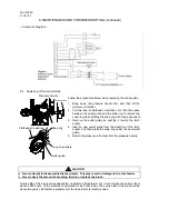
Replacing of the Outlet Guide 


Follow the procedures below when replacing the outlet guide. 
 
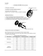
1.  Bring down the pressure handle first, and then lift the 

pressure roll holder. 

2.  Forcibly insert a flathead screwdriver, etc. into the space 

between the outlet guide and the snap ring to remove the 
snap ring while holding the snap ring with long-nose pliers. 

3.  Remove the outlet guide by pushing it toward the torch 

socket.  

4.  Insert a new outlet guide from the direction of the torch 

socket, and then place the snap ring under the new outlet 
guide.  

5.  Return the pressure roll holder first, the pressure handle. 


CAUTION


● 

Never attempt to disassemble the feed motor. This may result in damage to the wire feeder. 

● 

Never check the amount of brushing friction or replace the brush. 

 
Service life of the brush varies depending on ambient temperature, etc., but normally the service life is 
about 4,000 hours. (If the machine is operated for six hours a day, the service life of the brush will be 
about two years). Periodical replacement of the feed motor is recommended. 
 

Pressure handle 

Flathead screwdriver 

Long-nose pliers 

Outlet guide 

Snap ring 

Torch socket 

Summary of Contents for CM-7401

Page 1: ...before installing operating or maintaining this equipment This equipment and this manual are for use only by persons trained and experienced in the safety operation of welding equipment Do not allow u...

Page 2: ...WELDING SAFETY PRECAUTIONS 2 3 CHECKING OF QUANTITY OF THE ACCESSORIES 8 4 NAME OF PARTS 8 5 CARRYING AND INSTALLING OF THE WIRE FEEDER 9 6 CONNECTION PROCEDURE 10 7 WELDING PREPARATION 13 8 MAINTENAN...

Page 3: ...RNING ARC WELDING can be hazardous PROTECT YOURSELF AND OTHERS FROM POSSIBLE SERIOUS INJURY OR DEATH Be sure to Keep children away Keep pacemaker wearers away until consulting a doctor Read and unders...

Page 4: ...undersized or poorly spliced cables 8 Do not touch electrode and any metal object if POWER switch is ON 9 Do not wrap cables around your body 10 Turn off POWER switch when not in use ARC RAYS can burn...

Page 5: ...tip when not in use 10 Does not use the welding power source for other than arc welding 11 Wear oil free protective garments such as leather gloves a heavy shirt cuffless trousers boots and a cap 12 A...

Page 6: ...low instructions on compressed gas cylinders associated equipment and the CGA publication P 1 listed in PRINCIPAL SAFETY STANDARDS 7 Turn face away from valve outlet when opening cylinder valve 8 Keep...

Page 7: ...power source and wire feeder solidly on a flat surface Do not pull the welding power source across a floor laid with cables and hoses Do not put wire feeder on the welding power source Do not put the...

Page 8: ...dard AWS C5 2 from American Welding Society Recommended Safe Practices for the Preparation for Welding and Cutting of Containers That Have Held Hazardous Substances American Welding Society Standard A...

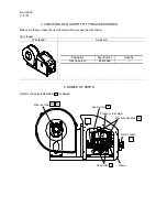
Page 9: ...w before you use the wire feeder Wire feeder Wire feeder Accessory 4 NAMES OF PARTS Refer to the page indicated in for details Pressure handles Wire reel hub Frame Torch socket Feed rolls Feed motor P...

Page 10: ...fume wear a gas mask or weld at a partial exhaust facility approved by the local regulation Adequately ventilate or wear a gas mask when using the welding machine in a tank a boiler a hold of a ship b...

Page 11: ...ed in Preparation of the parts except the standard composition is required to use the wire feeder Available in 5 m 10 m 15 m and 20 m Follow the steps below to connect to the welding power source and...

Page 12: ...he welding machine in such a humid environment as construction site on the steel plate or on steel structure install a leakage breaker CAUTION Use the proper torch cable that matches the welding curre...

Page 13: ...per gas flow rate regulator to the gas cylinder Failure to observe the demand may result in physical injuries The gas flow rate regulator for high pressure gas must be used How to Make Gas Connection...

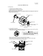
Page 14: ...prevent the cap knob from dropping 6 Bring down the pressure handle then raise the pressure roll holder 7 After pulling out the wire thread it from the pilot to outlet guide through the center guide...

Page 15: ...h the wire size marked on the wire feeder facing out Adjusting of the wire pressure and straightener Set to the proper wire pressure for the wire type by turning the pressure handle The numeral on the...

Page 16: ...the tip hole to check for the rate of wire feeding while inching CAUTION Keep away your hands fingers hair or clothes from the rotating parts of the feed roll etc to prevent you from being caught int...

Page 17: ...ts in the wire and wire feeder The parts indicated as in the figure are the charging parts during welding 7 5 Hanging the Wire Feeder CAUTION When hanging the wire feeder firmly fix the cap knob and c...

Page 18: ...contact and breakdown in the voltage detection cable Trouble with the motor Replace the motor with a new Wire pressure is too weak Refer to Recommended wire adjustment in Section 7 2 Dust and chip ar...

Page 19: ...new outlet guide from the direction of the torch socket and then place the snap ring under the new outlet guide 5 Return the pressure roll holder first the pressure handle CAUTION Never attempt to di...

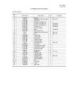
Page 20: ...5260C05 Panel 1 With coating and indicating plate 9 U5260B00 Wire feeder 1 With a feed motor 10 4739 549 Quick connector 1 FA3076 Red 11 4739 550 Quick connector 1 FA3086 Blue 12 4734 020 Cable connec...

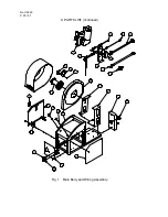
Page 21: ...No U5260 P 20 27 9 PARTS LIST continued Fig 1 Main Body and Wiring Assembly 4 5 3 2 1 8 6 7 20 21 12 13 14 15 18 17 16 22 9 19 25 10 24 23 11...

Page 22: ...socket cap screw 4 M4 x 16 9 2 None Bolt 4 M4 x 10 10 U5260B02 Guide block 1 11 U5185B05 Center guide 1 12 4802 206 Feed motor 1 13 U5185B06 Insulating board 1 14 U3971B04 Insulating bush 3 14 1 None...

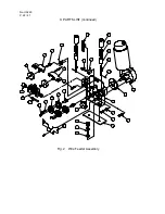
Page 23: ...No U5260 P 22 27 9 PARTS LIST continued Fig 2 Wire Feeder Assembly 24 8 9 20 25 23 17 16 19 12 13 1 14 22 21 15 7 5 3 2 4 11 10 18...

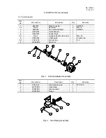
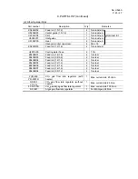
Page 24: ...04 Guide adaptor 1 4 U5260J03 Feeder block 1 4 1 None Hexagon Socket cap screw 1 M8 x 25 5 U5260J02 Outlet guide 1 E snap ring 5 1 3361 405 E snap ring 1 E 4 6 U5185D04 Small nut 1 Fig 3 Central Adapt...

Page 25: ...6012 BKPDJ 8012 When the power cable more than 12m is necessary please consult with the dealer When performing pulse welding using the welding power source with 350 A applicable current and a 17m or...

Page 26: ...er hose 2 1 7m K5439B01 Feed roll 1 4 1 6 2 for steel K5439B03 Feed roll 0 8 0 9 2 for steel K5439B04 Feed roll 1 2 1 4 2 for steel K5439B05 Feed roll 1 2 1 2 2 for steel K5439B06 Feed roll 1 4 1 4 2...

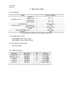
Page 27: ...wire Max 25kg Quantity 16 kg The wire feeder complies with the requirements of IEC974 5 10 2 Available Welding Torch EURO BINZEL TORCH Air cooling EURO BINZEL TORCH Water cooling 10 3 Combination Pow...

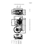
Page 28: ...CIFICATIONS continued External View of CM 7401 Wire Feeder unit mm Water connection Condensed water Water connection Supply water Euro central adaptor Wire feeder Cable connector 10P receptacle Gas co...

Reviews: