


28
GENERAL
External sensors, actuators, etc. are connected to the HERU
®
CX unit or to an expan-
sion model, supplied separately (see chapter 11).
Terminal numbers are grouped as follows:
Terminal no.
Cable’s max mm²
Group’s placing
Voltage
1-10
4
HERU
®
CX
≤ 230VAC
11-20
4
EXP1
≤ 230VAC
31-40
4
HERU
®
CX
≤ 230VAC
41-63
1
HERU
®
CX
≤ 50V
71-93
1
EXP1
≤ 50V
94-96
1
HERU
®
CX
Modbus RTU - RS485
97-100
1
HERU
®
CX & EXP1
≤ 50V/KNX (internal communication)
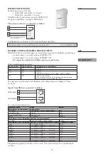
CONNECTION
The following example shows a HERU
®
T CX:
All terminals, except for the feeding power connections, are 2-level type.
2-LEVEL CONNECTION TERMINALS
Connection terminal
(beige)
Earth connection terminal
(green-yellow)
The external side on the bottom level is connected with the bottom level’s internal
side.
The external side on the top level is connected to the internal side’s top level.
The earth connection terminals, green-yellow, are all connected to each other and in
direct contact with DIN rail and thereby also in contact with the unit casing.
9. External components, basic unit
1...10
31...40
41...55
56...63
94...100
GND
Plint nr.:
1...10
31...40
41...55
56...63
94...100
GND
Terminal
no.:
1270466_utg3_HERU_400_1200_eng.indd 28
2020-10-28 11:59:44
1270466_utg3_HERU_400_1200_eng.pdf 28
2020-10-28 12:04:19