background image

One Stop Systems 


OSS-EOS-2U-4A | 24 


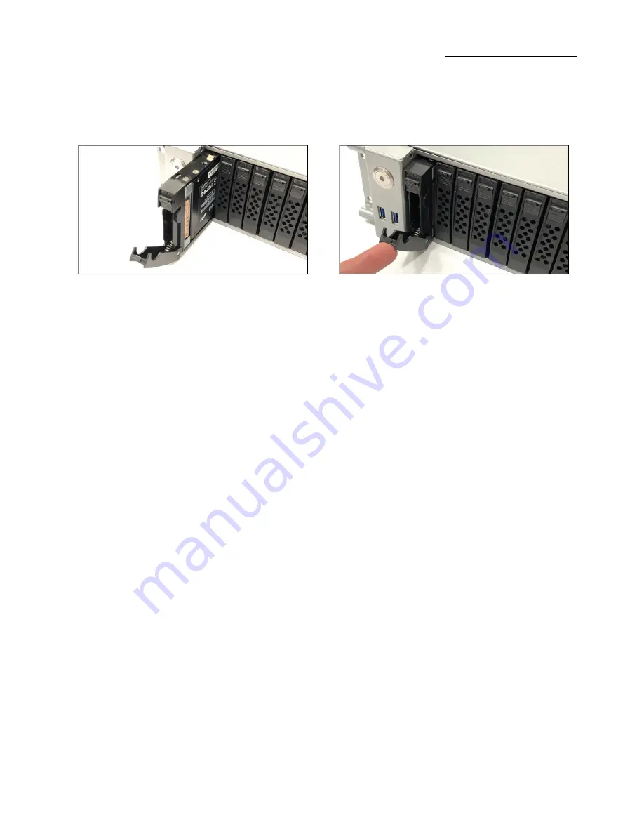
Insert the hard drive and drive carrier into its bay vertically, keeping the carrier correctly oriented so that the release button is on the top. 
When the carrier reaches the rear of the bay, the release handle will retract.  

Using the thumb, push against the upper part of the hard drive handle. Push the hard drive into the hard drive bay as illustrated below, until 
the hard drive clicks into the locked position. 


Summary of Contents for EOS-2U-4A

Page 1: ...User Manual 2U EOS Server OSS EOS 2U 4A SKU OSS EOS 2U 4A www onestopsystems com ...

Page 2: ...2 5 Storage Drive 22 4 1 Remove faceplate 22 4 2 Remove Drive Tray 22 4 3 Install Storage Drive 23 5 How to Set Up SATA Bootable Drive 25 5 1 Connect HD Mini SAS SFF 8643 cable 25 6 How to Set Up NVME SSD Bootable Drive 28 6 1 Connect Oculink Cable 28 7 Setup NVME SSD and M 2 NVME 29 8 Target Card Installation 30 9 Connecting OSS Expansion Unit 32 9 1 Connect LINK Cables 32 9 2 Power Up 33 10 M 2 ...

Page 3: ...top Systems OSS EOS 2U 4A 3 17 How to Update BMC Firmware via Web User Interface 48 18 Contacting Technical Support 52 19 Returning Merchandise to One Stop Systems 52 20 APPENDIX A Compliance 53 FCC 53 CE 53 ...

Page 4: ...ion or to alert you to the potential for hardware damage or personal injury Disclaimer We have attempted to identify most situations that may pose a danger warning or caution condition in this manual However One Stop Systems does not claim to have covered all situations that might require the use of a Caution Warning or Danger indicator ...

Page 5: ...a Computer Before taking covers off a computer perform the following steps Turn off the computer and any peripheral devices Disconnect the computer and peripheral power cords from their AC outlets or inlets in order to prevent electric shock or system board damage In addition take note of these safety guidelines when appropriate To help avoid possible damage to systems boards wait five seconds aft...

Page 6: ...ures which can include wrist straps and smocks when servicing equipment You can also take the following steps to prevent damage from electrostatic discharge ESD When unpacking a static sensitive component from its shipping carton do not remove the component s anti static packaging material until you are ready to install the component in a computer Just before unwrapping the anti static packaging b...

Page 7: ...2242 2260 2280 2x miniSAS HD 2x Oculink by jumper 1 x PCIe 3 0 x16 HHFL slot Storage Subsystem EOS configuration 24x hot swap configurable SATA 3 SAS 3 or NVMe x4 2 5 x 15mm drive carriers 12Gb SAS 3 6Gb SATA 3 SFF 8680 NVMe x4 32Gb slots Up to 8 SATA 3 slots use no PCIe slots 12x and 24x SATA SAS slots require 1 and 2 PCIe x16 HHHL slots respectively 8x and 16x NVMe x2 slots require 1 and 2 x16 P...

Page 8: ...rified to comply with Part 15 of the FCC Rules Class A Canada ICES 003 issue 4 Class A CE Mark EN55022 Class A EN55024 EN61000 3 2 EN61000 3 3 CISPR 22 Class A Designed to conform to the following extended standards NOM 019 Argentina IEC60950 1 Japan VCCI Class A Australia New Zealand AS NZS CISPR 22 Class A China CCC GB4943 GB9254 Class A GB17625 1 Taiwan BSMI CNS13438 Class A CNS14336 1 Korea KN...

Page 9: ...One Stop Systems OSS EOS 2U 4A 9 1 2 Overview ...

Page 10: ...One Stop Systems OSS EOS 2U 4A 10 ...

Page 11: ...One Stop Systems OSS EOS 2U 4A 11 1 3 Motherboard Layout ...

Page 12: ...One Stop Systems OSS EOS 2U 4A 12 1 4 Descriptions ...

Page 13: ...One Stop Systems OSS EOS 2U 4A 13 ...

Page 14: ...One Stop Systems OSS EOS 2U 4A 14 1 5 Quick Reference Table ...

Page 15: ...One Stop Systems OSS EOS 2U 4A 15 ...

Page 16: ...ics controller VGA support via ASPEED AST2600 BMC I O Devices Serial COM Port One serial port on the rear I O panel COM1 One front accessible serial port header COM2 SATA 3 0 Eight I SATA 3 0 ports at 6 Gb s I SATA0 3 I SATA4 7 Two Intel PCH powered S SATA 3 0 Ports with support for SuperDOM Disk on Module devices S SATA4 S SATA5 Video VGA Connections One VGA port on the rear I O panel VGA2 One VG...

Page 17: ...should perform the following steps Inventory the shipping carton contents Gather all the necessary tools required for installation Read this manual 1 8 Tools Required for Installation To complete the installation of the product you will need a Phillips head screwdriver and ESD wrist strap to prevent electrostatic discharge ...

Page 18: ...switch to power ON the unit 6 Login 2 2 Connect IO Cables Connect keyboard mouse video and ethernet cables to the unit 2 3 Power ON the Unit Connect the power cords Press the front switch button to turn ON the unit Upon powering ON the unit the following LEDs will illuminate Front LED will illuminate as solid AMBER YELLOW Power supply LEDs will illuminate as solid green Blinking green indicates th...

Page 19: ...19 3 4 Log in You can log in to the Linux or Windows system using the following account credentials Username oss Password oss 111 Username root Password oss123 You can erase the existing OS in the system and install your preferred OS ...

Page 20: ...vers Remove the screws located on each side of the panel see photos below on the location of the screws Remove the screw located on the rear end of the top cover see photo below Remove front top cover first Lift the front top cover up and slowly slide it out ...

Page 21: ...One Stop Systems OSS EOS 2U 4A 21 After removing the front top cover remove the back end top cover Stand right behind the unit using both hands push the cover and then lift it up ...

Page 22: ...nt faceplate or the front bezel Hold the front face plate from the right side as shown from the photos below and gently pull it to detach 4 2 Remove Drive Tray Locate the locking tab slide it to the left to unlock Pull the drive tray out from the unit by pressing the release button The drive tray handle will extend ...

Page 23: ...t B to the hard drive tray C Remove the dummy drive from the hard drive tray Place the hard drive tray on a flat stable surface such as a desk table or work bench Slide the hard drive into the tray with the gold connector facing upward see photos below Carefully align the mounting holes in the hard drive and the tray Secure the hard drive using all four screws ...

Page 24: ...rrectly oriented so that the release button is on the top When the carrier reaches the rear of the bay the release handle will retract Using the thumb push against the upper part of the hard drive handle Push the hard drive into the hard drive bay as illustrated below until the hard drive clicks into the locked position ...

Page 25: ...ct HD Mini SAS SFF 8643 cable Plug in the SFF 8643 cable to the onboard Mini SAS HD connector Plug in the other end of the cable to the drive midplane board Set the jumpers on the motherboard correctly to enable the Mini SAS HD connector photo below is the correct jumper settings ...

Page 26: ...front LED on the drive carrier will illuminate as green and blue During boot up hit or press the DEL key Go to the BIOS verify and confirm the SATA drive is detected In the BIOS select Advanced Tab check if the SATA drive is visible The example screenshot below shows the storage drive is detected ...

Page 27: ...One Stop Systems OSS EOS 2U 4A 27 Go to Boot tab select the SATA drive as Boot Option 1 or primary boot device Click Save and exit ...

Page 28: ... 4i to OcuLink SFF 8611 cable Plug in the Oculink cable to the onboard Oculink connector Plug in the other end of the cable to the external drive backplane To enable the Oculink connection allowing the NVME drive to be detected you need to set the jumpers on the motherboard properly photo below is the correct OCULINK jumper settings ...

Page 29: ...Systems OSS EOS 2U 4A 29 7 Setup NVME SSD and M 2 NVME To enable both Oculink OCU1 OCU2 and M 2_1 on ROMED8 2T MB the jumpers PE8_SEL PE16_SEL should be in pin2_3 NOTE The PCIE2 will be disable with this setting ...

Page 30: ... see How to Remove Top Cover section The PCIe host card is a half height x16 capable PCIe card mounted to a full height bracket as shown below For low profile case applications change the mounting bracket to the low profile bracket You can order a low profile bracket by contacting our Sales Support Replacing the High Profile Bracket with Low Profile Bracket is done by removing the screws that hold...

Page 31: ...ith a mounting screw Electrostatic Discharge ESD Warning All PCI cards are susceptible to electrostatic discharge When moving PCI cards it is best to carry the cards in anti static packaging If you need to set a PCIe card down be sure to place it inside or on top of an anti static surface For more information see Protecting Against Electrostatic Discharge in the Preface ...

Page 32: ...k cables Use the same model of Target and Host adapter cards i e OSS OSS PCIE HIB616 X16 9 1 Connect LINK Cables Plug in the cables i e SFF 8644 between host and target cards Connect the four x4 SFF 8644 cables to the target card installed in the expansion unit Connect the other end of the cables to the host card Cable diagram below shows how to connect all four SFF 8644 cables between Host and Ta...

Page 33: ...s to the expansion unit The expansion unit will power UP instantly Other expansion units will require you to manually turn the power switch ON Connect power cable s to the computer Turn On the computer Upon powering UP the computer it will initialize a link between host and target ...

Page 34: ...ove the mounting screw located across from the M 2 slot Step 2 Align the M 2 Key edge connector to the M 2 key edge socket on the board Step 3 Slowly insert the media at 30 degree position into the socket until it is fully seated The SSD will naturally stand at an angle when inserted this is normal See photos below Step 4 Secure the M 2 SSD using the mounting screw Press down and hold the M 2 SSD ...

Page 35: ...me motherboards will automatically detect an M 2 SSD but when that does not happen you will need to manually go to the BIOS and set the settings that an M 2 device is connected 1 Power UP the computer during the boot up process press Delete to enter BIOS 2 Go to Advanced Tab select and select Storage Configuration you should see the M 2 detected 3 Go to NVME Configuration it will show the NVME dri...

Page 36: ...One Stop Systems OSS EOS 2U 4A 36 ...

Page 37: ...One Stop Systems OSS EOS 2U 4A 37 ...

Page 38: ...OSS EOS 2U 4A 38 11 How to Remove Power Supply Pressing and holding the lever towards your right and gently pull the handle to remove power supply module CAUTION Turn OFF the unit first before removing the power supply ...

Page 39: ...e power supply housing to have physical access to the CPU and memory modules Remove the PSU modules Remove the two mounting screws underneath the metal enclosure Remove the two mounting screws on the back of the unit see photos below Remove the three mounting screws located on the side of the unit see photo below ...

Page 40: ...One Stop Systems OSS EOS 2U 4A 40 Remove the air baffle Slowly raise the PSU housing and lay it flat on the top surface of the unit ...

Page 41: ...One Stop Systems OSS EOS 2U 4A 41 13 How to Remove the Fan 1 Loosen up the screw 2 Grasp the fan on both sides 3 Lift the fan 4 Pull the fan away from mounting bracket ...

Page 42: ...stall the Fan 1 Align the two metal tabs on top of the two notches 2 Align the two fan connectors 3 Slowly push the fan down 4 Check both tabs are fully seated 5 Tighten up the screw to secure the fan 6 Photo below shows the fan is seated properly ...

Page 43: ... 2U 4A 43 Make sure the fan is installed Use photos below as reference on how to check if the fan is installed and secured properly Verify the screw is tightened see photos below Verify the fan is fully seated see photos below ...

Page 44: ...otherboard follow the instructions below Plug in an Ethernet cable to the MGMT port see photo below Power up the SDS system during boot up the BMC IP address will show up on the screen see photo below as example Start your internet browser and enter the BMC IP address see screenshot below Login as Admin password is Admin ...

Page 45: ...r Interface Login to BMC Click Maintenance Cick BIOS Update This wizard will take you through the process of firmware upgrades Click the Browse to select the BIOS FW file Then click Start BIOS update to start the upgrade process Click OK if confirmed to continue the process ...

Page 46: ...One Stop Systems OSS EOS 2U 4A 46 FW verification processing please wait a few second Click Proceed to continue the BIOS FW upgrade process Then click OK to start the actual BIOS FW upgrade operation ...

Page 47: ...stems OSS EOS 2U 4A 47 FW upgrade is processing please wait a few second BIOS FW upgrade process finished Click OK to reload the webpage NOTE Clear the browser cookies after the BIOS FW upgrade process is finished ...

Page 48: ...One Stop Systems OSS EOS 2U 4A 48 17 How to Update BMC Firmware via Web User Interface Click Maintenance Click Firmware update ...

Page 49: ...One Stop Systems OSS EOS 2U 4A 49 ...

Page 50: ...One Stop Systems OSS EOS 2U 4A 50 ...

Page 51: ...One Stop Systems OSS EOS 2U 4A 51 ...

Page 52: ...required you must contact OSS Service Representative to obtain a Return Merchandise Authorization RMA number Put this number and your return address on the shipping label when you return the item s for service One Stop Systems will return any product that is not accompanied by an RMA number Please note that One Stop Systems WILL NOT accept COD packages so be sure to return the product freight and ...

Page 53: ...Operation is subject to the following two conditions 1 this device may not cause harmful interference and 2 this device must accept any interference received including interference that may cause undesired operation Changes or modifications not expressly approved by the party responsible for compliance could void the service personnel s authority to operate the equipment NOTE The assembler of a pe...

Page 54: ...One Stop Systems OSS EOS 2U 4A 54 ...

Reviews: