


www.osram-os.com
9 / 18
2020-06-04 | Document No.: AN149
For the connection to the heat sink, please use thermal interface material (for
detailed information on thermal interface material, please refer to Application
Note “AN053_Thermal management of OSRAM OSTAR
®
Projection light
sources”). The devices can be connected to the heat sink with a screw.
When mounting the MPCB to the frame or heatsink by means of a screw, metric
cylindrical head screws M1.4 can be used for the mounting and it is generally
recommended that a locking compound are used for each screw. When
mounting the screws (M1.4), it is recommended that you check on the maximum
torque with the screw supplier. Additionally, to avoid MPCB bending which can
have an adverse effect on the thermal interface material and the LED itself, a
maximum torque of 0.2 Nm should be used. There are 4 holes on the MPCB, and
it is recommended to use 2 diagonal holes for mounting and another 2 holes for
aligning them with the register pins.
Assembly of the connector
In order to be able to connect the individual components, the IMS provides pins
for assembling a connector. The recommended connector for each component
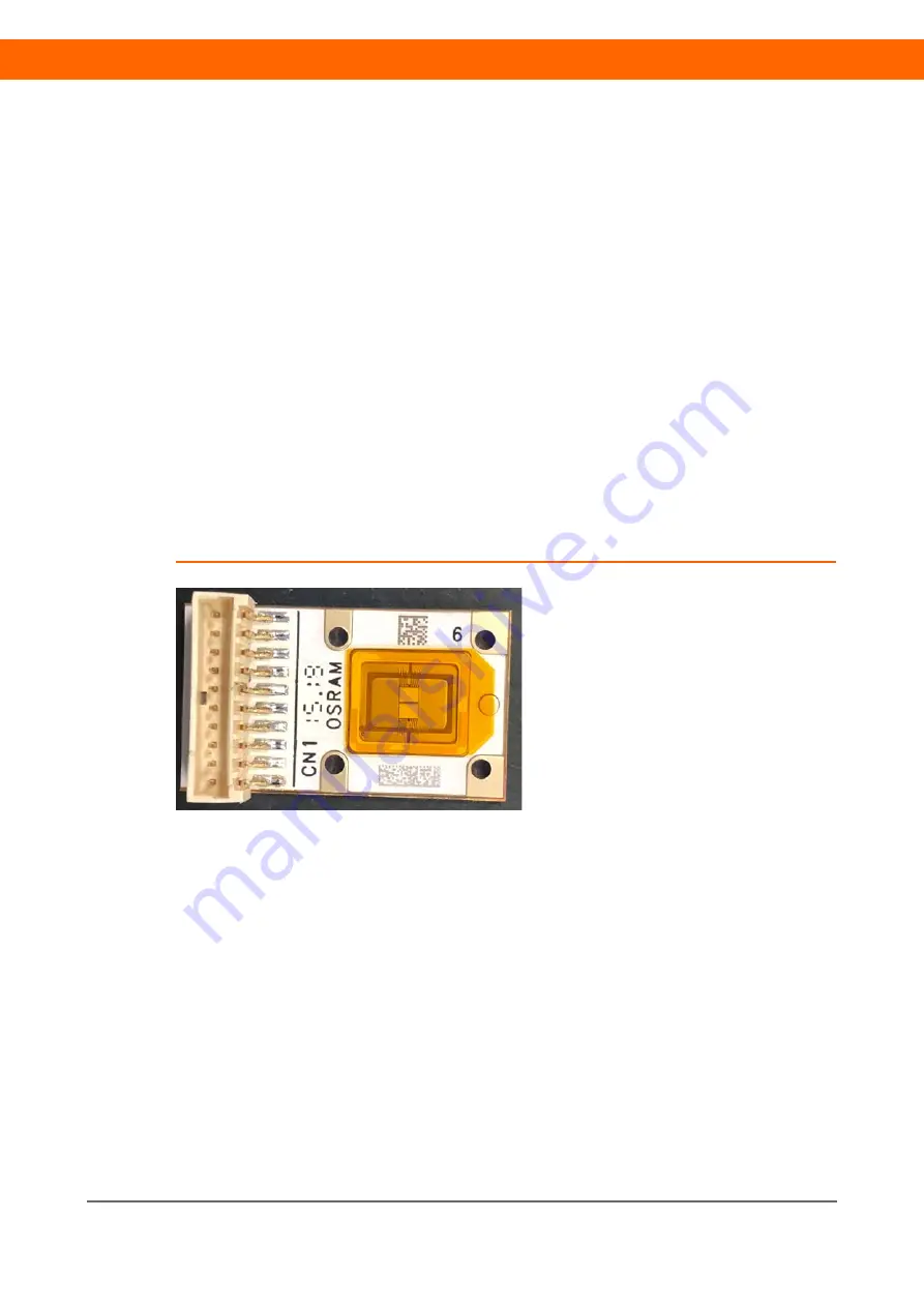
can be found in the respective data sheet. Figure 9 shows an assembled
connector.
Figure 9: Assembled connector
It is common in industry to use carriers or pallets for the entire SMT assembly
process (solder paste printing, connector placement, reflow soldering) when
processing PCB-based components. These carriers are typically made of highly
heat-resistant, fiber-reinforced material. The cut-outs, which fit the component
precisely, hold the components in place. This enables a stable and reproducible
assembly with a good soldering process. Figure 10 shows a sketch of a possible
carrier.


