


8
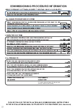
2.10 Pipe connections
Before connecting the cold supply (3), flush the
cold supply pipework of all flux and debris. Lift off
the cylinder lid to allow access to the combina-
tion valve and other connections.
2.11 Vessel connections
Check the expansion vessel(s) and hose connec-
tions are tight. SX 300: Fit the expansion vessel
and bracket on a suitable wall close to the cyl-
inder.
2.12 Remove the template
Position the cylinder to meet the heating and do-
mestic water pipes.
2.13 Combination valve
The combination valve at the top of the cylinder
is factory fitted and is water-tight. If necessary it
can be rotated in either direction to suit the con-
necting pipework, up to half a turn without losing
its seal.
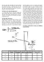
2.14 Cold mains supply
Connect the cold mains supply to the combi-
nation valve cold feed (see illustration below).
The OSO unvented unit is designed for use with
supply pressure up to 8 bar. For water pressures
above 8 bar an additional pressure reducing valve
must be fitted to the cold water supply pipe.
2..15 Hot water outlet
Connect the hot water distribution pipe to the
combination valve hot water outlet (see illustra-
tion).
2.16 Balanced cold water supply (optional)
If no balanced cold supply is required, tighten the
supplied blanking cap.
!
Do not use the balanced cold connection
to feed any outlets other than mixer showers.
Under no circumstances use the balanced cold
connection to feed all cold water outlets as
this practice contravenes Section 10 of water
regulations.
!
If a balanced mains pressure cold water supply is
required to a shower or bidet (over rim type only,
ascending spray type requires type AA, AB or AD
air gap), remove blanking cap and connect to the
shower or bidet cold supply (2) on the combina-
tion valve. Major shower manufacturers advise
fitting a mini expansion vessel in the balanced
cold supply pipework to accommodate thermal
expansion and prevent tightening of shower con-
trols.
2.17 Expansion vessel (300 l. only)
Site the expansion vessel on the wall using the
supplied bracket and connect to the expansion
vessel connecting point (13) on the multifunction
valve with copper pipe.
2.18 Flexible Y-hose
The flexible Y-hose (11) is preformed to the cor-
rect shape. Connect the inlet ends to the expan-
sion relief valve (6) and the temperature and
pressure relief valve (8).
2.19 Tundish
Recommended position of the tundish (12) is to
the left of the cylinder as seen from the front.
Connect the tundish inlet to the outlet end of the
flexible Y-hose (11). Tundish should be visible and
positioned away from electrical devices. Tundish
can be secured with supplied screws.
2.20 Secondary return (optional)
If a secondary return is connected reduce ther-
No. Description
Dim.
1
Domestic hot water outlet (DHW out)
ø22 mm
2
Balanced cold water connection (Bal. CW) ø22 mm
3
Cold water main supply inlet (CW in)
ø22 mm
1 2
3
13
8
11
12
6