background image

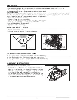
Install ceiling material to complete the ceiling construction. Then, cut around 

the fan housing.

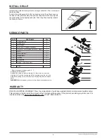
To attach the grille assembly to the fan housing, pinch the grille springs on 

the sides of the grille assembly, and position the grille into the housing with 

the grille springs in the appropriate slots. Push the grille assembly towards 

the ceiling to secure.

WARRANTY

INSTALL GRILLE

SERVICE PARTS

PART

PART NAME

Qty.

1
2
3
4
5
6
7
8
9

10

Housing

Blower Wheel

Wire Panel / Harness Assembly

Motor

1
2
1
1
1
1
1
4
1
1

11

a

Damper / Duct Connector

1

1

Motor Plate

Grille Assembly 
Grille Spring

* Blower Assembly includes part 3, 6, 7. 

Replacement installation:

Remove the screw on motor plate (part 3), then take out the motor 

plate (part 3) from the housing (part 9) by pushing down the rib in the 

plate while pulling out on the side of the housing. Replace the broken 

parts.

4

WARNING: 

Before replacing, be sure to turn off power at power source.

A

1

2

3

4

6

5

7

8

8

9

10

a

11

Hanger Bars

Humidity Sensor system (for sensor model)

Wiring plate

Screw

ONE YEAR LIMITED WARRANTY from the original date of purchase against defects in material and workmanship. 

This warranty is limited up to the amount of the original purchase price of the product, excluding any labor cost. For 

inquiries please visit www.ortechindustries.com or call 1-888-543-6473.

Summary of Contents for OD-5006

Page 1: ...ion in ceilings up to a 12 12 pitch 45 degree angle Duct connector must point up DO NOT MOUNT THIS PRODUCT IN A WALL 3 To avoid motor bearing damage and noisy and or unbalanced impellers keep drywall...

Page 2: ...operation by turning on the shower or other humidity source until the fan turns on 5 Repeat above steps if necessary When the temperature changes humidity sensor values will have deviation TIMER ADJU...

Page 3: ...m of the housing is even with the finished ceiling Extend the hanger hars to the joist Use screws to secure the hanger bars to the ceiling joists DUCT 3 ATTACH DAMPER DUCT CONNECTOR Snap the damper du...

Page 4: ...ssembly Grille Spring Blower Assembly includes part 3 6 7 Replacement installation Remove the screw on motor plate part 3 then take out the motor plate part 3 from the housing part 9 by pushing down t...

Page 5: ...OD 5006 OD 5006HS OD 8011 OD 8011HS Four Model OD 5006HS OD 8011HS VENTILATEUR AVERTISSEMENT PRECAUTION L ENTRETIEN ET LE NETTOYAGE FONCTIONNEMENT 5...

Page 6: ...ez l chement le bo tier la solive en ins rant des vis bois dans les encoches en trou de serrure des languettes de montage R glez la position du bo tier de fa on ce qu il soit au m me niveau que le pla...

Page 7: ...UR L ASSEMBLAGE 2 INSTALLATION AVEC BARRES DE SUSPENSION Ins rez les barres de suspension dans les fentes du bo tier Placez le bo tier du ventilateur entre les solives de fa on ce que le bord inf rieu...

Page 8: ...t de pi ces Enlevez la vis puis retirez la plaque du moteur pi ce 3 du bo tier en poussant la nervure vers le bas tout en tirant sur le c t du bo tier pi ce 9 Remplacez les pi ces d fectueuses PI CE N...

Reviews: