


1. History
2
2. Purpose
2
3. General
2
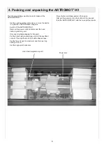
4. Packing and unpacking the ARTROMOT®-K1
5. Block diagram of the electronic
parts ARTROMOT®-K1
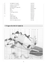
6. Bill of material for service parts ARTROMOT®-K1
7. Figure for bill of material
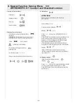
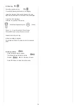
8. Special function Service menu for
ARTROMOT®-K1Comfort and Standard version
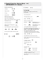
9. Special function Service menu for
ARTROMOT®-K1Classic
10. How to perform repairs
11. Checklist of safety and function test
ARTROMOT®-K1Comfort and Standard version
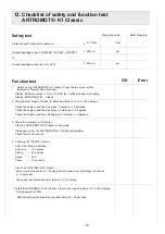
12. Checklist of safety and function test
ARTROMOT®-K1Classic
5
6
7
8
10
12
14
15
16
2
The purpose of this Service Manual is to help you make
simple repairs on the ARTROMOT®-K1. Only authorized
staff may perform repairs and maintenance as the manufac-
turer’s warranty and liability would otherwise be invalidated.
Only original parts may be used for servicing in accordance
with the attached spare parts list.
3.1 Electronics, connection cables
1
2
3
4
No plugs may be connected or disconnected while the
unit is switched on. Always switch the ARTROMOT®-K1
off before connecting or disconnecting a plug.
The locks for spiral cable for the hand-held program-
ming unit have to be closed at all times.
When you assembling with electronic parts make sure
to use ESD (Electro Static Discharge) equipment.
Only original chip cards may be used. Insert the chip
cards so that ARTROMOT® is visible.
If you have to exchange any of the printed circuit boards
including the knee electronics, hand held programming
unit, motor control or power supply electronics you have
to perform a calibration.
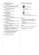
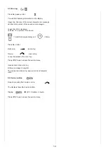
Possible errors: Errors will be displayed on the hand-
held programming unit as follows shown:
Potentiometer error:
Wrong angle information
->
Check the femur settings
->
Replace knee electronics (Pos. 5)
->
Replace motor control (Pos. 25)
Failure at the potentiometer:
Connection to the potentiometer is interrupted
->
Replace the spiral cable of the potentiometer (Pos. 24)
->
Replace knee electronics (Pos. 5)
->
Replace motor control (Pos. 25)
Motor driver error:
The motor driver IC reported an error
->
Replace motor control (Pos. 25)
Motor error:
The motor did not turn properly
->
Replace motor control (Pos. 25)
->
Replace the motor (Pos. 26)
Table of contents
2. Purpose
1. History
Revision
Date
Name
Change
1
10.02.2006
S. Herr
Service Manual
created
2 14.07.2006 S. Herr
Pos. 25,
chapter 10
3 14.08.2006 S.Herr
Pos. 20,
Chapter 9, 12
3. General
ERROR
XX
(XX = Number of the error)


