background image

4

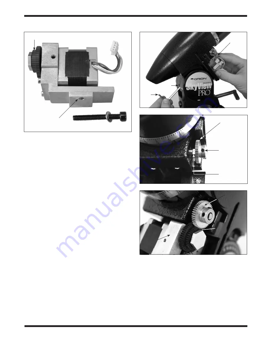
the R.A. GoTo motor. Place one of the 10mm flat wash-
ers onto the R.A. motor attachment screw. Attach the R.A. 
motor attachment screw to the end of a 4mm hex key and 
push it up through the hole in the rear of the equatorial 
mount (

Figure 4).  Hold the R.A. GoTo drive in your hand 

so its threaded hole meets the screw as it comes out the 
other end of the hole. Thread the screw into the threaded 
hole of the R.A. motor assembly until secure, but do not 
overtighten. You will need to make small adjustments to 
the motor position in the following steps. 

4.   Slide the geared end of one of the small brass gears onto 

the worm gear shaft so it resembles 

Figure 5. Rotate the 

small brass gear so that one of the setscrews will press 
against the flat part of the R.A. worm gear shaft.  Secure 
the small brass gear by tightening the setscrews with the 
included 2mm hex key, but do not overtighten. You may 
have to make small adjustments to the gear’s position in 
the following step to ensure proper gear engagement. 

5.   Make certain that the teeth of the 

smaller motor assem-

bly gear correctly mesh with the teeth of the brass gear 
(

Figure 6). Also, make certain the gears are not too tightly 

pressed together. You may have to adjust the way the gears 
mesh by tightening or loosening the socket-head cap screw 
that is used to attach the R.A. GoTo motor assembly to the 
mount and/or the small setscrews on the brass gear. If the 
gears are not meshed correctly or are too tightly pressed 
together, then the drive will not track properly, or at all. This 
attachment process is tricky, and it may take several adjust-
ments before the gears properly mesh.

6.  Take the R.A. GoTo motor cover and hold it near the 

installed R.A. GoTo motor. On the inside of the motor 
cover, you will see a set of wires with a white 4-pin rectan-
gular connector attached. Carefully connect the 4-pin rect-
angular connector attached to the R.A. GoTo motor cover 
to the corresponding 4-pin rectangular connector on the 

R.A. GoTo motor. Once connected, the wiring of your R.A. 
GoTo motor should resemble 

Figure 7.

Note: Inside the R.A. GoTo motor cover you will find an addi-
tional set of wires connected to each other with 5-pin rectan-
gular connectors. Make certain these wires are connected 
before proceeding to step 7.

7.   Once the rectangular connector has been attached, you 

can install and secure the R.A. GoTo motor cover with the 
10mm long Phillips head screw. Don’t forget to re-install 
the rear latitude adjustment L-bolt if you have removed it 
previously.

Figure 4. 

Attaching the R.A. GoTo motor

Figure 5. 

Correct orientation of brass gear for R.A. axis

Hole

4mm

hex 

key

Brass gear

Setscrew

R.A.  
worm gear 
shaft

Brass gear

Small R.A. GoTo 

motor gear

R.A. 
GoTo 
motor

Figure 6. 

Correctly meshed gears (R.A.)

R.A. 
GoTo 
motor

Figure 3. 

The R.A. GoTo motor assembly

4-pin rectangular 
connectors

R.A. GoTo motor attachment screw

Attachment 

hole

Smaller gear

Summary of Contents for SkyView Pro GoTo System

Page 1: ...ffices 89 Hangar Way Watsonville CA 95076 USA Providing Exceptional Consumer Optical Products Since 1975 Copyright 2018 Orion Telescopes Binoculars All Rights Reserved No part of this product instruction or any of its contents may be reproduced copied modified or adapted without the prior written consent of Orion Telescopes Binoculars ...

Page 2: ...em not all parts on parts list are shown Motor control box bracket R A GoTo motor cover Dec GoTo motor Motor control box GoTo hand controller bracket GoTo hand controller Motor cables GoTo hand controller cable R A GoTo motor Brass gears ...

Page 3: ...led All slow motion adjustments will be made using the GoTo hand controller 3 The R A GoTo motor assembly is identified by the 4 pin rectangular connector attached to the motor body Figure 3 The motor will be attached to the mount by a 40mm long socket head cap screw that goes through the hole in the rear of the equatorial mount just above the rear latitude adjustment L bolt Figure 4 It will be he...

Page 4: ... the mount and or the small setscrews on the brass gear If the gears are not meshed correctly or are too tightly pressed together then the drive will not track properly or at all This attachment process is tricky and it may take several adjust ments before the gears properly mesh 6 Take the R A GoTo motor cover and hold it near the installed R A GoTo motor On the inside of the motor cover you will...

Page 5: ...ve the Dec Motor cover from the Dec motor assembly Figure 9 Once the screws have been removed pull the cover off the motor There will be some friction resistance but it should pull off by hand Save the cover and screws in a safe place to reinstall after the motor is attached 3 Slide the geared end of the remaining small brass gear onto the Dec worm gear shaft of your SkyView Pro mount Figure 8 Cor...

Page 6: ...correctly or are too tightly pressed together then the drive will not track properly or at all This attachment process is tricky and it may take several adjustments before the gears properly mesh Note There is a small packet of grease included with your SkyView Pro GoTo system Once you have installed the GoTo motor so the gears mesh properly you can apply a very small amount of the included grease...

Page 7: ...dly menu allows automatic slewing to over 42 000 p 3objects Even inexperienced astronomers will find themselves quickly mas tering the variety of features the GoTo hand controller offers in just a few observing sessions For more information about the features and functionality of the SynScan GoTo Hand Controller refer to the separate manual for the controller Powering the SkyView Pro GoTo System T...

Page 8: ... instrument has been abused mishandled or modified nor does it apply to normal wear and tear This warranty gives you specific legal rights It is not intended to remove or restrict your other legal rights under applicable local consumer law your state or national statutory consumer rights governing the sale of consumer goods remain fully applicable For further warranty information please visit www ...

Reviews: