background image

16 


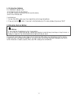
6.4 Replacing UPS Internal Batteries 

Follow the steps and Charts as below to replace batteries: 


1.  Take off the LCD box, and remove the screws. 


2.  Slide and pull the front panel leftward and then take it off. 


3.  Disconnect the cable from the UPS and battery pack.   


4.  Remove the right inner battery bracket.   


5.  Pull the battery pack out onto flat area. 


6.  Install new battery pack into UPS.   
7.  Screw up the battery bracket and reconnect the battery cable A and B 


8.  Re-install the front panel back to UPS. 

Summary of Contents for Network Pro 1500 RTX

Page 1: ...USER GUIDE Network Pro 1500 RTX Network Pro 2200 RTX Line Interactive UPS Uninterruptible Power Supply System ...

Page 2: ...structions for NP1500RTX NP2200RTX that should be followed during installation and maintenance of the UPS and batteries Please read all safety and operating instructions before operating the UPS Adhere to all warnings on the unit and in this manual Follow all operating and user instructions ...

Page 3: ...REEN FUNCTION 13 5 COMMUNICATION PORT 14 5 1 RS 232 AND USB COMMUNICATION PORTS 14 5 2 EMERGENCY POWER OFF EPO SET UP 14 5 3 NETWORK MANAGEMENT CARD OPTIONAL 15 5 4 USB FOR HID POWER DEVICE 15 6 UPS MAINTENANCE 15 6 1 UPS AND BATTERY CARE 15 6 2 STORING THE UPS AND BATTERIES 15 6 3 TIME TO REPLACE BATTERIES 15 6 4 REPLACING UPS INTERNAL BATTERIES 16 6 5 TESTING NEW BATTERIES 17 6 6 RECYCLING THE U...

Page 4: ... Dry contact RS 232 USB communication port SNMP allows for web based remote or monitoring management Enable to extend runtime with scalable external battery module EBM Overload short circuit and overheat protection Rack Tower 2 in 1 Design 19 inches rack mount available for all models 2 Safety Warning DANGER This UPS contains high voltages All repairs and service should be performed by authorized ...

Page 5: ...batteries in a fire Batteries may explode when exposed to flame Following figure shows the basic internal circuit configuration of the UPS 2 1 Description of Commonly Used Symbols Some or all of the following Notations may be used in this manual and may appear in your application process Therefore all users should be familiar with them and understand their explanations Table1 Description of Common...

Page 6: ...kaging in a responsible manner or store it for future use 3 3 UPS Setup All model series are designed for tower and rack purpose They can be installed into a 19 inches equipment rack Please follow the instruction for Tower Setup and Rack Mount Setup Tower setup This series of UPS can be placed horizontally and vertically As a tower configuration it is provided with the optional UPS stands to stabi...

Page 7: ... mount setup The series can be installed in 19 inches racks Both the UPS and external battery enclosure need 2U of valuable rack space Use the following procedure to install UPS in a rack 1 Align the mounting ears with screw holes on the side of the UPS and tighten the screw 2 Assemble the rack rails with the rack mounting ...

Page 8: ...7 3 Slide in the UPS into the rack rail and lock it in the rack enclosure 4 Tighten the screw and the load can then be connected ...

Page 9: ...ith the extend part at each end of the tower 2 Tighten the screw on the metal sheet for stabilization 3 Connect EBM port C to UPS port D with one of the accessory wire Connecting the EBM in a rack form 1 Using the same method as assembling UPS in a rack form assemble EBM into the rack mounting on the top or bottom of the UPS ...

Page 10: ...nput power cord The UPS front panel display illuminates and UPS status display shows STbY 4 Press and hold the button more than 3 seconds The UPS status display changes to NORM 6 Check the UPS display for active alarms or notices Resolve any active alarms before continuing See Troubleshooting 8 If optional EBMs are installed see Configuring UPS for EBM numbers on page 17 to set the number of insta...

Page 11: ...onds To release the UPS from faulty mode Cut off input power and then press and hold the button more than 2 seconds to shut down the UPS UPS Test Alarm Silence To perform basic function test Press and hold the button for 3 seconds To perform Battery life test Press and hold the button for 10 seconds To disable alarm buzzer Press the button for one second Select Press the Select button to select th...

Page 12: ... Output frequency and voltage Indicates the value of output frequency and voltage Output plug indicator The UPS has three groups of outlets The output plug indicator will light on if there is output power respectively LS3 is the main outlet and cannot be configured UPS status user setting display String Strings Indicate the UPS status see Table 4 Strings Indicate user setting options see Table 5 W...

Page 13: ...o high bATL Battery voltage is too low OVTP Internal temperature is too high FNLK Fan is locked bTWK Batteries are weak SITE Site fault No protective ground or L N reverse User Setting String Description The following table shows the options that can be changed by user Table5 User Setting String OPV Output voltage mode select 120V AVR Input type select 000 Normal range mode 001 Wide range mode 002...

Page 14: ...d the settings string will flash 4 Select setting value Press the Select button to select the settings value Select the value 001 or 000 to set the desired load segment ON or OFF 5 Confirm settings Press and hold the Enter button for one second ups will return to current setting item 6 Exit Settings mode Press and hold the Enter button for 3 seconds or button for 0 5 second to exit setting mode 4 ...

Page 15: ...er to be shut down the protected equipment immediately and does not follow the shutdown procedure from any power management software Note When EPO switch is reset the equipment will not return to battery power until the UPS is manually restarted If pressing power switch to turn off UPS after EPO is activated the UPS remains in Standby mode when restarted until pressing power switch to turn on the ...

Page 16: ...the batteries charge for 48 hours after long term storage 6 3 Time to Replace Batteries When LCD backlight turns to red the screen displays bTWK and there is a continuous sounding the battery may need to be replaced Please check the battery connection or contact your local dealer to order new battery WARNING Turn off the UPS and disconnect the utility power cord from the wall outlet Servicing shou...

Page 17: ... Slide and pull the front panel leftward and then take it off 3 Disconnect the cable from the UPS and battery pack 4 Remove the right inner battery bracket 5 Pull the battery pack out onto flat area 6 Install new battery pack into UPS 7 Screw up the battery bracket and reconnect the battery cable A and B 8 Re install the front panel back to UPS ...

Page 18: ... Recycling the Used Battery Warning Never dispose the batteries in a fire It may explode Do not open or mutilate the batteries Released electrolyte is harmful to the skins and eyes It may be toxic A battery can present a risk of electrical shock and high short circuit current To recycle the used battery properly please do not discard the UPS battery pack and batteries into the trash bin Please fol...

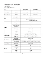
Page 19: ...ation Batt Mode 5 Frequency 50Hz or 60Hz Output Waveform Pure sine wave Line Mode 110 10 shutdown after 3 minutes 150 10 shutdown after about 200ms Overload rating Battery Mode 110 10 shutdown after 30 seconds 120 10 Shutdown after about 100ms Battery Type Lead Acid Battery Typical Backup Time at full PFC load 3 Internal battery Recharge Time 3 hours from 10 to 90 after discharged 2 hours from 10 ...

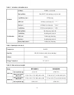
Page 20: ...d Sounding every second Audible alarm Battery Replacement Continuously Sounding Table 9 Operating Environment Temperature 0 to 40 C Humidity 20 80 relative humidity non condensing Altitude 2000m Storage Temperature 15 to 45 C Table 10 Dimensions and weights Model NP1500RTX NP2200RTX Net weight lbs kg 41 88 19 47 39 21 5 UPS Case Dimension in mm W x H x D 17 24 x 3 40 x 17 16 438 x 86 5 x 436 17 24...

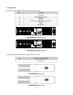
Page 21: ...REAR PANEL LAYOUT The EBM rear panel description table and picture are shown below NP1500RTX EBM rear panel NP2200RTX EBM rear panel No Function 1 AC Output 2 External battery connector 3 SNMP Port 4 AC Input 5 RS232 Dry Contact Communication Port 6 USB Port 7 EPO 8 Earth Line Port No Function 36V 48V EBM 1 Ground Line Port ...

Page 22: ...The UPS can t be turned on when power switch is pressed Internal fuse may be broken Please contact your local dealer Output jumpers is not connected correctly Check output jumpers UPS is on and no power to load No power on LS1 and LS2 output receptacle Check if the LS1 and LS2 are set up from 001 to 000 Battery is empty Re charge the battery at least 24 hours Backup time is short Battery aging Rep...

Page 23: ...er must appear on the outside of the box and on the Bill Of Lading Original packaging should be used if available Systems that get damaged in transit as a result of improper packaging are not covered under warranty A replacement or repair unit will be shipped freight prepaid for all units under warranty NOTE For critical applications immediate replacement may be available Product Registration Prod...

Reviews: