New Multi Function Controller
12
| ORION CO., LTD.
ORION CO., LTD. |
13
05-3. AUTO Tracking
(MFC-4250)
It is available only with PC mode. When it is connected with DVI converter,
Auto Tracking is used to correct the distorted screen alignment.
1) Press AUTO button.
2) Auto Tracking is performed.
05-4. DVI Selector
(MFC-4250)
It is used to select DVI 1 input or DVI 2 input.
1) Press DVI 1 or DVI 2 buttons in the Remote controller.
2) When the LED is turned on, product output is DVI 1 and when it is
turned off product output is DVI 2.
05-5. Model Select
(MFC-4260)
This function is used to select the e-Board Model.
X x Y configuration is automatically set.
1) Select the installed e-Board Model.
- 117" is 3 x2 configuration
- 84" is 2x2 configuration.
05-6. Mode Select
(MFC-4260, MFC-MLCD)
This function is various.
1)
F1
: Display individual screen on the E-Board.
2)
F2
: Display full screen on the E-Board.
3)
F3
: Return X x Y configuration to previous status.
4)
F4
: Execute the Auto tracking function(PC Input only).
REMOTE CONTROL
ON
OFF
INFO
A
SET
DVIC1
DVIC2
INFO
AUTO
VIDEO S-VIDEO HDSDI
DVI
PC
DTV
HDMI
B
BROADCAST
ID SETTING
ON
OFF
1
2
3
4
5
6
7
8
0
9
DVI 1
DVI 2
OUTPUT
FUNCTION
INPUT SELECT
REMOTE CONTROL
ON
OFF
INFO
A
SET
DVIC1
DVIC2
INFO
AUTO
VIDEO S-VIDEO HDSDI
DVI
PC
DTV
HDMI
B
BROADCAST
ID SETTING
ON
OFF
1
2
3
4
5
6
7
8
0
9
DVI 1
DVI 2
OUTPUT
FUNCTION
INPUT SELECT
REMOTE CONTROL
ON
OFF
INFO
A
SET
F1
F2
F3
F4
VIDEO
DVI
PC
117"
84"
B
BROADCAST
ID SETTING
ON
OFF
1
2
3
4
5
6
7
8
0
9
MODEL
SELECT
MODE SELECT
INPUT SELECT
E-BOARD
REMOTE CONTROL
ON
OFF
INFO
A
SET
F1
F2
F3
F4
VIDEO
DVI
PC
117"
84"
B
BROADCAST
ID SETTING
ON
OFF
1
2
3
4
5
6
7
8
0
9
MODEL
SELECT
MODE SELECT
INPUT SELECT
E-BOARD
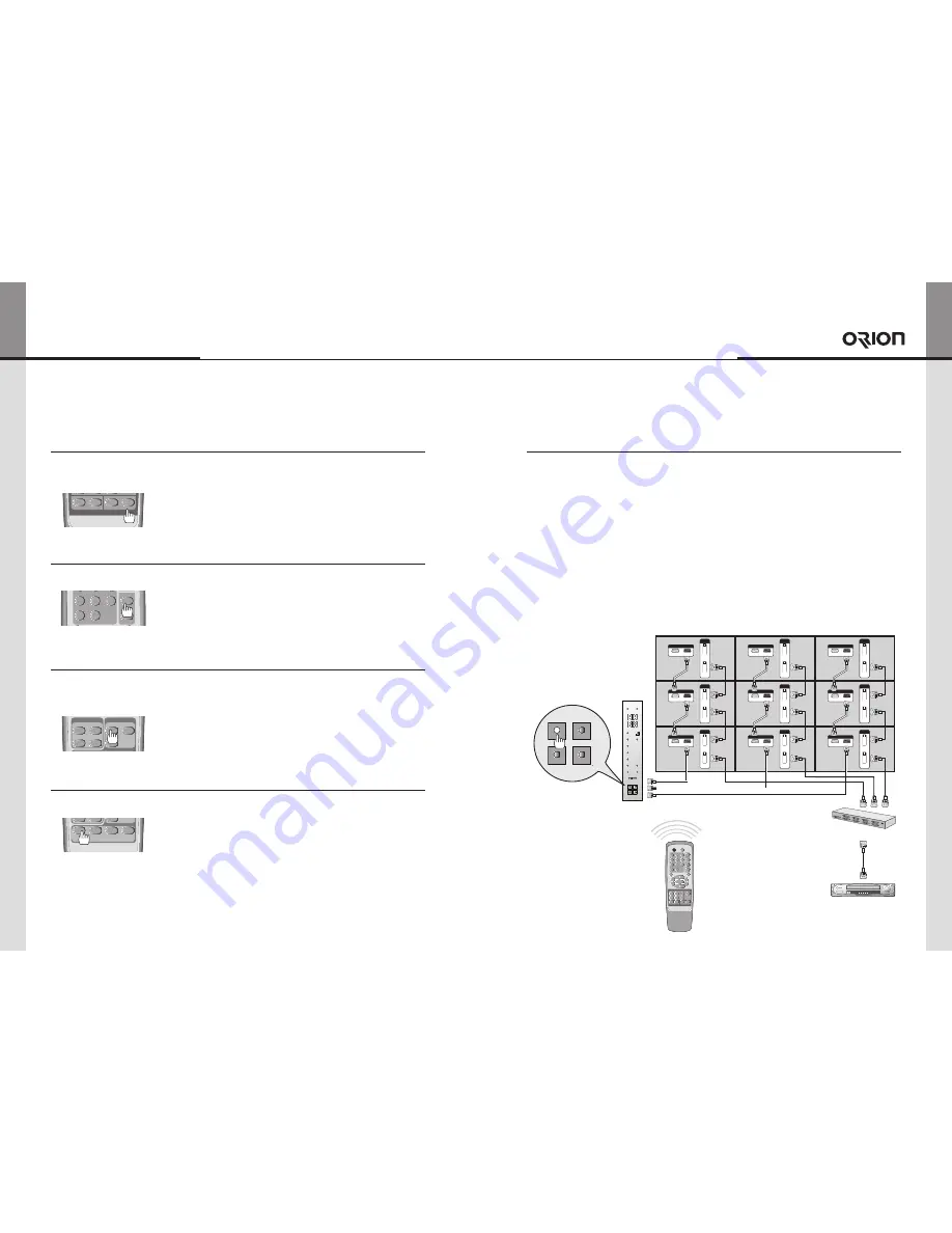
05-7. Communication Mode change
There are four interface, Ethernet, USB, RS-232C, and IR (Remote control).
Users can select the mode
Press one of the four LED switches to select a mode you want.
1. IR mode
IR interface is designed to execute some product commands through the wireless infrared
communication. It includes some tests and functions to configure Ethernet settings. The
signal from the remote controller is converted to RS-232C signal as defined in the protocol
and send to product.
1) To execute IR mode, press IR LED switch on the front side of New MFC.
2) When you press, IR LED switch, the other communication modes are not working.
3) For better IR performance, product set configuration is necessary. Configure the number of
"X" and "Y" as installed.
ID 1
ID 4
ID 7
ID 2
ID 5
ID 8
ID 3
ID 6
ID 9
DVI-D_1
INPUT
OUTPUT
DVI-D_1
INPUT
OUTPUT
DVI-D_1
INPUT
OUTPUT
DVI-D_1
INPUT
OUTPUT
DVI-D_1
INPUT
OUTPUT
DVI-D_1
INPUT
OUTPUT
DVI-D_1
INPUT
OUTPUT
DVI-D_1
INPUT
OUTPUT
DVI-D_1
INPUT
OUTPUT
RS-232C
INPUT
OUTPUT
RS-232C
INPUT
OUTPUT
RS-232C
INPUT
OUTPUT
RS-232C
INPUT
OUTPUT
RS-232C
INPUT
OUTPUT
RS-232C
INPUT
OUTPUT
RS-232C
INPUT
OUTPUT
RS-232C
INPUT
OUTPUT
RS-232C
INPUT
OUTPUT
PWR ON
PWR OFF
DVI
HOR
VER
IR
PC
DVI 1/2
DTV
VIDEO
S-VIDEO
HDSDI
HDMI
DVIC1
DVIC2
IR
RS232
ETHERNET
USB
New MFC
RS-232C
DVI Signal Distributor
(UXGA : UP TO 165MHz)
Remote Controller
REMOTE CONTROL
ON
OFF
INFO
A
SET
DVIC1
DVIC2
INFO
AUTO
VIDEO S-VIDEO HDSDI
DVI
PC
DTV
HDMI
B
BROADCAST
ID SETTING
ON
OFF
1
2
3
4
5
6
7
8
0
9
DVI 1
DVI 2
OUTPUT
FUNCTION
INPUT SELECT
IR
RS232
ETHERNET
USB


