background image

7   

INSTRUCTION  MANUAL

RESOLUTION

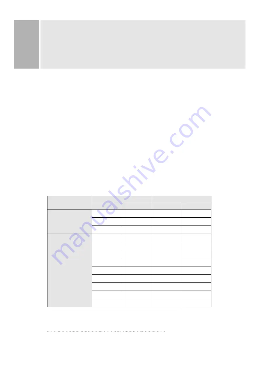
This monitor is a digitally-controlled multi-frequency monitor.

It operates at horizontal frequencies of 30 to 96KHz and vertical

frequencies of 50 to 160Hz.

Because of its micro processor-based designs it offers auto-synchronization

and auto-sizing capabilities. This monitor offers 12 programmed settings

as listed in the table below.

These 12 preset modes cover most of the common video modes supported by

popular graphic adaptors. However, each adaptors implementation of these

video modes may vary slightly in timings. You may find it necessary to make

minor adjustments to the display settings (i.e., horizontal position) using

the On Screen Display. For further information and instructions on using

the On Screen Display, please refer to Section 5. “Controls and Functions.”

You can also program any signal within its frequency range of 30-96KHz

horizontal and 50-160Hz vertical as user Programmed modes.

PRESET  MODES

VGA

VESA

RESOLUTION

FREQUENCY

H(Pixels)

V(Lines)

H(KHz)

V(Hz)

640

350

31.5

70

720

400

31.5

70

640

480

31.5

60

640

480

43.2

85

800

600

46.9

75

800

600

53.6

85

1024

768

68.7

85

1152

864

67.5

75

1280

1024

64.0

60

1280

1024

80.0

75

1600

1200

81.3

65

1600

1200

93.7

75

Summary of Contents for F9S936

Page 1: ...USER S MANUAL MODEL No F9S936 BEFORE USING THIS COLOR MONITOR READ AND OBSERVE ALL OF THIS USER S MANUAL 19 DIGITAL COLOR MONITOR...

Page 2: ...UCTION 2 CAUTIONS 4 FCC RF INTERFERENCE STATEMENT 5 INSTALLATION 6 RESOLUTION 7 CONTROLS AND FUNCTIONS 8 REAR VIEW 13 POWER MANAGEMENT 14 SPECIFICATIONS 15 TROUBLE SHOOTING GUIDE 16 This Monitor was M...

Page 3: ...s product should be operated from the type of power source indicated on the marking label If you are not sure of the type of power available consult your dealer or local power company 9 This product i...

Page 4: ...ied technician to restore normal operation E If the product has been dropped or the cabinet has been damaged F If the product exhibits a distinct change in performance indicating a need for service C...

Page 5: ...over the unit or place anything on the top of unit Ventilation holes are provided also on the bottom of the cabinet AVOID HEAT AVOID HEAT Avoid placing the unit in direct sunshine or near a heating ap...

Page 6: ...r more of the following measures Reorient or relocate the receiving antenna Increase the separation between the equipment and receiver Connect the equipment into an outlet on a circuit different from...

Page 7: ...graphic card on back of the computer 2 Secure the connection with the screws on the plug 2 CONNECT THE POWER CORD Connect the female end of the power cord to the power input receptacle on the back pa...

Page 8: ...f these video modes may vary slightly in timings You may find it necessary to make minor adjustments to the display settings i e horizontal position using the On Screen Display For further information...

Page 9: ...ates and exits the On Screen Display This button can also be used to move previous menu or status There are two OSD menu or status They are USER MENU 1 H POSITION H SIZE V POSITION V SIZE PIN CUSHION...

Page 10: ...at is selected and activated blinking via the select button Press the Adjust button A window containing an adjustment bar will increase or decrease After completing all the desired adjustments the On...

Page 11: ...H POSITION Horizontal Position Moves images horizontally on screen left or right H SIZE Horizontal SIze Increases or decreases Size of image horizontally V POSITION Vertical position Moves images ver...

Page 12: ...om color mode select USER and push the select button to activate the RGB Sub menu This adjust the intensity of the RGB video output Using the select button activate the RG Red Gain GG Green Gain or BG...

Page 13: ...terns V MOIRE ADJUST Reduces the optical effect of vertical wavy lines on the display image These effects are usually more noticeable on large gray areas or on black white check board patterns DEGAUSS...

Page 14: ...er cord is used as main power disconnect device in this product F D SUB CONNECTOR OF SIGNAL CABLE Connect to the analog RGB signal output connector of video card ACCESSORY 1 POWER CORD 2 INSTRUCTION M...

Page 15: ...each of the three modes of the signaling system POWER CONSUMPTION LED INDICATOR The power management feature of the monitor is comprised of four stages On Green Standby Suspend Amber blinking and Acti...

Page 16: ...0 160Hz INPUT SIGNAL INPUT SIGNAL VIDEO Analog 0 7Vp p 75 SYNC Separate and Composite TTL Level ACTIVE DISPLAY AREA W x H ACTIVE DISPLAY AREA W x H Preset 346mm X 255mm Full 366mm X 275mm DIMENSIONS W...

Page 17: ...microprocessor of the monitor The sound you hear indicates that the demagnet izing circuit is activated Every time the monitor is powered on it will go through the degaussing process which helps elimi...

Reviews: