5
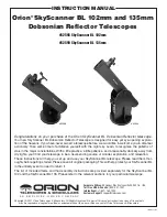
Both the altitude and azimuth axes of the SkyScanner BL are
equipped with tension adjustment knobs, which you installed
earlier. These should be adjusted so there is sufficient friction
of motion to keep the telescope from rotating too freely in each
axis, which can make it difficult to land on and stay aimed at
an object you wish to view. However, if you apply too much
tension the telescope will be difficult to move smoothly and in
small increments needed to center an object in the eyepiece
for viewing.
Focusing the Telescope
Both SkyScanner BL telescopes come equipped with a rack-
and-pinion focuser. The SkyScanner BL 102mm has a 1.25"
focuser, which accepts only eyepieces with 1.25"-diameter
barrels. The SkyScanner BL 135mm model comes with a 2"
focuser that has a 1.25" adapter installed in it. This focuser can
accept eyepieces with either 2"-diameter barrels or 1.25" barrels.
To use an optional 2" eyepiece in the SkyScanner BL 135mm,
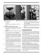
you must first remove the 1.25" adapter from the focuser (
Figure
22
). To do so, just loosen the thumbscrew until it is nearly all
the way out, then the adapter can be removed. Place the 2"
eyepiece’s barrel into the drawtube collar and tighten it with the
thumbscrew.
We recommend practicing focusing in the daytime when starting
out to get the hang of it. With the 25mm eyepiece inserted into
the focuser and secured with the thumbscrew, aim the optical
tube so the front (open) end is pointing in the general direction
of an object at least 1/4-mile away. With your fingers, slowly
rotate one of the focus wheels until the object comes into sharp
focus. Go a little bit beyond sharp focus until the image starts to
blur again, then reverse the rotation of the knob gradually, until
you’ve nailed the exact focus point.
Aligning and Using the Red Dot Finder Scope
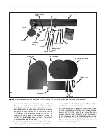
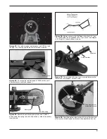
The included red dot finder scope (
Figure 9
) makes pointing
your telescope almost as easy as pointing your finger. It permits
easy object targeting prior to observation in the higher-power
main telescope. It superimposes a red dot generated by an inter-
nal LED light on the sky, showing right where your telescope is
pointed (
Figure 23
).
Before you can use the red dot finder scope, you must remove
the small tab sticking out from the battery compartment. Doing
so will allow the pre-installed 3V CR-2032 button cell battery to
make contact with the finder scope’s electronic circuitry to power
the finder’s red LED illuminator. The tab can then be discarded.
To use the red dot finder scope properly, it must be aligned with
the main telescope. This is easiest to do during daylight hours,
before observing at night. Follow this procedure:
1. First, remove the dust cover from the front of the tele-
scope.
2. With the 25mm eyepiece installed in the focuser, point the
telescope at a well-defined land target (e.g., the top of a
telephone pole) that’s at least a quarter mile away.
3. Center the target in the eyepiece.
Note:
The image in the eyepiece will appear rotated (upside
down). This is normal for reflector telescopes.
4. Turn on the red dot finder scope by sliding the power
switch to ON (refer to
Figure 9B
). The power switch actu-
ally has two illumination settings: the middle position
Azimuth
adjustment
knob
Altitude
adjustment
knob
Drawtube collar
Power switch
Focuser
Figure 9. A)
Install the red dot scope by sliding the bracket into the
base as shown.
B)
The power switch has two brightness settings.
Figure 10.
Insert an eyepiece into the focuser and secure it with
the thumbscrew.
A
B
Summary of Contents for 52598
Page 15: ...15 ...

