9
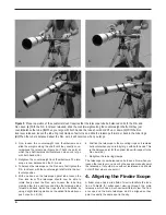
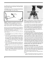
the setting circle lines up with the pointed indicator that is
cast into the mount (located directly below the large
setscrew; see Figure 3). Retighten the set screw.
2. Rotate the date circle until the “0” line on the meridian off-
set scale lines up with the time meridian indicator mark.
The meridian offset scale is printed on the inner circum-
ference of the date circle, and is labeled “E20” to “W20”.
The time meridian indicator mark is an engraved line on
the exterior of the polar finder’s housing. It is on the “ring”
of the housing that is closest to the date circle.
3. The R.A. setting circle is labeled in hours, from “0” to “23”
(military time). For Northern Hemisphere observers, refer
to the top numbers on the setting circle. Each small line
represents 10 minutes of R.A. The date circle is labeled
from “1” to “12,” with each number representing a month of
the year (“1” is January, “2” is February, etc.). Each small
line represents a two-day increment.
4. Loosen the R.A. lock lever and rotate the mount about the
R.A. axis until the March 1 indicating mark (the long line
between the “2” and the “3”) on the date circle lines up with
the 4 PM mark (the long line above the “16”) on the R.A.
setting circle. You may find it convenient to remove both the
counterweights and the telescope optical tube to do this.
5. Now, loosen the three setscrews on the polar finder hous-
ing and rotate the polar finder so the small circle where
Polaris will be centered is located straight down from the
intersection of the crosshairs. Retighten the set screws.
The polar axis finder scope is now properly set in its initial
position. Next, we must align it so that it is exactly parallel to
the mount’s R.A. axis:
6. Look through the polar finder at a distant object (during the
day) and center it on the crosshairs.You may need to adjust the
latitude adjustment T-bolts and the tripod position to do this.
7. Rotate the mount 180° about the R.A. axis. Again, it may be
convenient to remove the counterweights and optical tube first.
8. Look through the polar finder again. Is the object being
viewed still centered on the crosshairs? If it is, then no fur-
ther adjustment is necessary. If not, then look through the
polar finder while rotating the mount about the R.A. axis.
You will notice that the object you have previously cen-
tered moves in a circular path. Use the three set screws
on the housing to redirect the crosshairs of the polar find-
er to the apparent center of this circular path. Repeat this
procedure until the position that the crosshairs point to
does not rotate off-center when the mount is rotated in
R.A. Once this is accomplished, retighten the set screws.
The polar axis finder scope is now ready to be used. When not in
use, replace the plastic protective cover to prevent the polar find-
er from getting bumped, which could knock it out of alignment.
Using the Polar Axis Finder
When using the polar finder in the field at night, you will need a
red flashlight, like the Orion RedBeam LED (#5744), to illumi-
nate the finder’s reticle. Shine the flashlight at an angle into the
front opening in the R.A. axis. Do not shine it directly into the
opening, or the light will be too bright, and you will also obstruct
the view of the polar finder. It may be helpful to have a friend
hold the flashlight while you look through the polar finder.
For most accurate polar alignment, you will need to know the
approximate longitude of your observing site.This information can
be obtained by looking at a local map. Now, you must figure the
difference between the longitude of your observing site and the
closest standard time meridian. The standard time meridians are
75°, 90°, 105°, and 120° for the 48 continental states (150° and
165° for Hawaii and Alaska). Choose the standard time meridian
that is closest in value to your local longitude, and then calculate
the difference. If your local longitude has a value less than the
closest standard time meridian, then you are east of the standard
time meridian by the calculated amount. If your local longitude
has a value greater than the closest standard time meridian, then
you are west of the standard time meridian by the calculated
amount. For example, if you are in Las Vegas, which has a longi-
tude of 115°, then the closest standard time meridian is 120°. The
difference between these two numbers is 5°. Since Las Vegas’
longitude value is less than the standard time meridian value, you
are 5° east of the closest time meridian.
Take your calculated difference from the closest standard time
meridian and rotate the date circle so that the meridian offset scale
line that corresponds to your calculated difference lines up with the
engraved time meridian indicator mark on the polar finder housing.
Each line of the meridian offset scale represents 5° of longitude.
Lines to the left of the “0” on the meridian offset scale indicate east
of the closest standard time meridian, while lines to the right of the
“0” indicate west of the closest standard time meridian. Continuing
with the prior example of observing in Las Vegas, you would rotate
the date circle so that the first line to the left of the “0” on the merid-
ian offset scale lines up with the time meridian indicator mark.
Make sure that the “0” mark on the R.A. setting circle lines up
with the pointed indicator cast into the mount, and that the
large set screw just above it is tightened. Now, rotate the
mount about the R.A. axis of the mount until the line on the
R.A. setting circle that corresponds to your current local time
lines up with the line on the date circle that indicates the cur-
rent date. If you are on daylight savings time, subtract one
hour from your current local time. For example, if it was
November 1 at 9 PM, you would rotate the telescope in R.A.
until the line above the “21” on the R.A. setting circle lines up
with the long line between the “10” and “11” on the date circle.
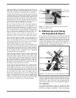
Finally, look through the polar alignment finder scope while shin-
ing a red flashlight at an angle down the front opening of the R.A.
axis, and center Polaris in the small circle. Do this by rotating the
tripod left or right, and adjusting the tilt of the R.A. axis up-or-down
with the latitude adjustment T-bolts. When you are close, you can
use the azimuth fine adjustment knobs for final positioning.To use
the azimuth fine adjustment knobs, you will first need to loosen
the big knob directly underneath the base of the equatorial mount.
Once Polaris is centered in the small circle, you are done. The
telescope is now accurately polar aligned, and can be used
for advanced observational applications, such as astropho-
tography or precise use of the manual setting circles. As
mentioned before, only move the telescope along the R.A.


