ORION PDP MIS-4201 User Manual Download Page 16

29

30

Infinitely expandable 

Multi-PDP

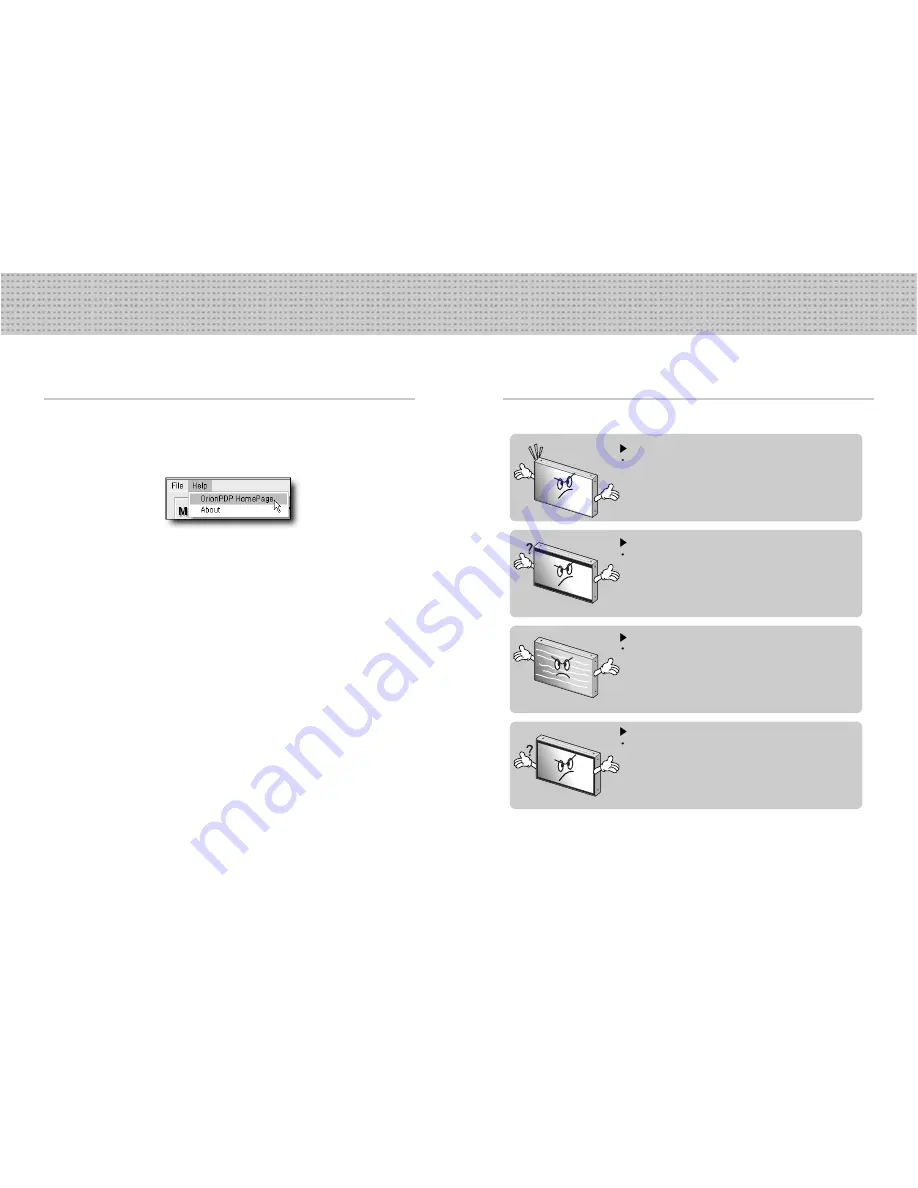
6.1 Before considering as a failure

Before calling for any repair, check the following and then refer to a near A/S center.

6. Other tips

“Tick” sound from the main body.

If there is no problem with the screen or sound, the “tick” sound is likely
to result from the cabinet lightly shrinking with the change of room
temperature.  The sound does not affect product’s performance.

No image at upper and bottom part of the screen.

As for a screen which is over 16:9 in width (such as cinema-sized one),
no image may be displayed at upper and bottom part of the screen.

Speckles or white lines on the screen

Check whether the problem is caused by vehicle, streetcar, high-
voltage cable or neon sign, which emitting interference wave or
electromagnetic induction.  Avoid any interfering object.

Screen size can be changed.

The screen size may be fitted to the first dark scene depending on
contents.

5.8 Orion PDP HOME PAGE

• If you are in connection with the Internet, you can reach our URL clicking Help and Orion

PDP Home Page.

Orion PDP HOME PAGE

Summary of Contents for MIS-4201

Page 1: ...ndable multi PDP Thank you for your purchasing our Multi PDP Please read through this user s manual for safety before installing this product This product is manufactured for Multi Plasma display mode...

Page 2: ...for business purpose with a safety certificate for electromagnetic interference which user should be mindful of Contents User s Manual Multi Screen Control System MSCS Power Cable Guide Pin 4pcs RS232...

Page 3: ...ar any heating device It may shorten product s life span or cause failure Make sure the product is not covered with any object If the venting hole is blocked the inside temperature may rise to cause o...

Page 4: ...he product with holding the handle and the front part at the same time How to move Multi PDP long distance Attach the transfer gripe to each side of the product Transfer gripe Handles 2 people move th...

Page 5: ...to the optional Wall Mounting Bracket Installation and Setup Guide Mount on the wall Wall mount allowing minimum clearance for adequate ventilation 3 Guidance for Users Front view Back view DVI D OUT...

Page 6: ...AC INPUT 1 RS 232C Multi PDP Control Firmware Upgrade 9pin D sub 2 Video Composite Signal NTSC PAL SECAM 3 S Video S Video Signal NTSC PAL SECAM 4pin Mini Din 4 Component DVD Signal DTV YPbPr Signal...

Page 7: ...gh PC the Identity number of each Multi PDP and that of MSCS should be identical RS 232C of each Multi PDP and PC should be connected DVI D OUT RS 232C IN RS 232C OUT DVI D IN VIDEO IN OUT S VIDEO IN...

Page 8: ...OUT S VIDEO IN OUT PC IN OUT COMPONENT IN OUT DVI D OUT RS 232C IN RS 232C OUT DVI D IN VIDEO IN OUT S VIDEO IN OUT PC IN OUT COMPONENT IN OUT AC INPUT 1 2 3 4 5 6 7 8 Pr Pb Y VCR Connection PC MSCS t...

Page 9: ...OUT PC IN OUT COMPONENT IN OUT AC INPUT 1 2 3 4 5 6 7 8 Pr Pb Y 1 2 3 4 5 6 7 8 DVD DTV Connection PC MSCS to control Multi PDP DVD DTV RS 232C COM1 When connecting to Component Component Input ports...

Page 10: ...D OUT RS 232C IN RS 232C OUT DVI D IN VIDEO IN OUT S VIDEO IN OUT PC IN OUT COMPONENT IN OUT AC INPUT 1 2 3 4 5 6 7 8 DVI D OUT RS 232C IN RS 232C OUT DVI D IN VIDEO IN OUT S VIDEO IN OUT PC IN OUT C...

Page 11: ...1 2 3 4 5 6 7 8 1 2 3 4 5 6 7 8 1 2 3 4 5 6 7 8 1 2 3 4 5 6 7 8 1 2 3 4 5 6 7 8 1 2 3 4 5 6 7 8 1 2 3 4 5 6 7 8 1 2 3 4 5 6 7 8 1 2 3 4 5 6 7 8 1 2 3 4 5 6 7 8 1 2 3 4 5 6 7 8 1 2 3 4 5 6 7 8 1 2 3 4...

Page 12: ...ct the Input Source and press the Play button Select a connected external Input Source and press the Play button The overall screen is played on the selected external unit if pressing the Play button...

Page 13: ...ti PDP 3 5 4 Set several screens at a time You can configure diverse screens as you want Select a desirable Input Source in Select Input Ex Select DVI in Select Input Click a desirable screen in Scree...

Page 14: ...Set command If alignment does not fit give Auto Tracking Detail command to control Frequency Phase Line Start Pixel Start in detail Adjusting steps are as follows 1 Adjust Phase until you can have cle...

Page 15: ...by pressing the Lode button Select a Input source for image adjustment Select a PC to control PC screen Click the White Balance button Graphic Video Dialog is displayed You can adjust the image on the...

Page 16: ...bottom part of the screen As for a screen which is over 16 9 in width such as cinema sized one no image may be displayed at upper and bottom part of the screen Speckles or white lines on the screen Ch...

Page 17: ...ay panel The followings are phenomena caused by characteristics of the plasma display panel Since it is not any failure you may use it at rest Black or twinkling spots on the screen Although the plasm...

Page 18: ...idity 20 70 Signal Video signal NTSC PAL SECAM PC signal VGA SVG A XGA SXGA UXGA Frequency Horizontal Frequency 15 5 75kHz Vertical Frequency 50 75Hz Connectors Input Output Video CVBS BNC S Video DIN...

Reviews: