


25
26
Infinitely expandable
Multi-PDP
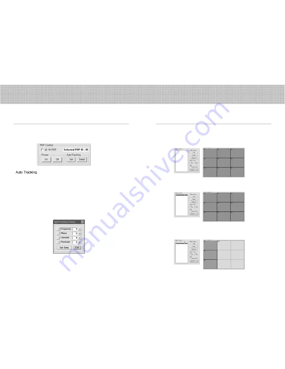
5.6 Slide Control
• Set the slide show list as you want. It can be repeated.
Select a desirable screen arrangement in Screen Configurations.
-Select a desirable screen arrangement and input source.
Input playing time in Slide Control.
-Input display time and save the data by pressing the Add button.
Save diverse screen arrangements in the same way.
-Set diverse types of display screen.
1
2
3
•
If pressing the Auto Tracking Set button, the Input Source executes command only in PC.
-After operating Auto Tracking Set command, If alignment does not fit, give Auto Tracking
Detail command to control Frequency, Phase, Line Start Pixel Start in detail.
Adjusting steps are as follows;
1) Adjust “Phase” until you can have clear vertical lines.
2) After adjusting “Phase”, adjust “Linestart” to fit vertical alignment, “Pixelstart” for horizontal
alignment.
3) Adjust “Frequency”, if you still have wrong alignment.
If you adjust “Frequency”, repeat step 1) and 2) to fit alignment.
-The range where you can adjust is from -50 to 50.
• The Selected PDP ID indicates activated PDP ID in Screen Configuration
(red rectangular area)
5.5 Use “PDP Control”
• Transmit PDP Control Data to selected ID of M-PDP.
• If checking ‘all M-PDP” box, the Data will be sent to all connected M-PDP, disregarding PDP ID.