5
z
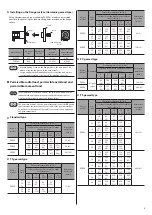
Installing on the flange surface (Harmonic geared type)
With a Harmonic geared type (excluding
PKE596
), a load can be installed
directly to the gear using the load mounting holes provided on the flange
surface.
Metal plate
Frange
Bolts
Load
Load mounting
holes
Motor model
Nominal
size
Number of
bolts
Tightening
torque
[N·m (oz-in)]
Effective depth
of bolt thread
[mm (in.)]
PKE543
M3
6
1.4 (198)
5 (0.2)
PKE564
M4
6
2.5 (350)
6 (0.24)
y
When installing a load on the flange surface, the load cannot be
affixed using the key groove in the output shaft.
y
Design an appropriate installation layout so that the load will not
contact the metal plate or bolts used for installing the motor.
Permissible radial load, permissible axial load and
permissible moment load
If the radial load or axial load exceeds the specified allowable value,
repeated load applications may cause the motor output shaft or
bearing (ball bearings) to undergo a fatigue failure.
The permissible radial load and permissible axial load of the
PS
geared
type represent the value that the service life of the gear part satisfies
20,000 hours when either of the radial load or axial load is applied to
the gear output shaft.
z
Standard type
Motor
model
Gear
ratio
Permissible radial load [N (lb.)]
Permissible
axial load
[N (lb.)]
Distance from the tip of motor’s output
shaft [mm (in.)]
0
(0)
5
(0.2)
10
(0.39)
15
(0.59)
20
(0.79)
PKE54
−
35
(7.8)
44
(9.9)
58
(13)
85
(19.1)
−
15 (3.3)
PKE56
90
(20)
100
(22)
130
(29)
180
(40)
270
(60)
30 (6.7)
PKE59
260
(58)
290
(65)
340
(76)
390
(87)
480
(108)
60 (13.5)
z
TS
geared type
Motor
model
Gear
ratio
Permissible radial load [N (lb.)]
Permissible
axial load
[N (lb.)]
Distance from the tip of motor’s output
shaft [mm (in.)]
0
(0)
5
(0.2)
10
(0.39)
15
(0.59)
20
(0.79)
PKE54
3.6
7.2
10
20
(4.5)
30
(6.7)
40
(9)
50
(11.2)
−
15 (3.3)
20
30
40
(9)
50
(11.2)
60
(13.5)
70
(15.7)
−
Motor
model
Gear
ratio
Permissible radial load [N (lb.)]
Permissible
axial load
[N (lb.)]
Distance from the tip of motor’s output
shaft [mm (in.)]
0
(0)
5
(0.2)
10
(0.39)
15
(0.59)
20
(0.79)
PKE56
3.6
7.2
10
120
(27)
135
(30)
150
(33)
165
(37)
180
(40)
40 (9)
20
30
170
(38)
185
(41)
200
(45)
215
(48)
230
(51)
PKE59
3.6
7.2
10
300
(67)
325
(73)
350
(78)
375
(84)
400
(90)
150 (33)
20
30
400
(90)
450
(101)
500
(112)
550
(123)
600
(135)
z
FC
geared type
Motor
model
Gear ratio
Permissible radial load [N (lb.)]
Permissible
axial load
[N (lb.)]
Distance from the tip of motor’s output
shaft [mm (in.)]
0
(0)
5
(0.2)
10
(0.39)
15
(0.59)
20
(0.79)
PKE54
All gear
ratios
180
(40)
200
(45)
220
(49)
250
(56)
−
100 (22)
PKE56
270
(60)
290
(65)
310
(69)
330
(74)
350
(78)
200 (45)
z
PS
geared type
Motor
model
Gear
ratio
Permissible radial load [N (lb.)]
Permissible
axial load
[N (lb.)]
Distance from the tip of motor’s output
shaft [mm (in.)]
0
(0)
5
(0.2)
10
(0.39)
15
(0.59)
20
(0.79)
PKE54
5
70
(15.7)
80
(18)
95
(21)
120
(27)
−
100 (22)
7.2
80
(18)
90
(20)
110
(24)
140
(31)
−
10
85
(19.1)
100
(22)
120
(27)
150
(33)
−
25
120
(27)
140
(31)
170
(38)
210
(47)
−
36
130
(29)
160
(36)
190
(42)
240
(54)
−
50
150
(33)
170
(38)
210
(47)
260
(58)
−
PKE56
5
170
(38)
200
(45)
230
(51)
270
(60)
320
(72)
200 (45)
7.2
200
(45)
220
(49)
260
(58)
310
(69)
370
(83)
10
220
(49)
250
(56)
290
(65)
350
(78)
410
(92)
25
300
(67)
340
(76)
400
(90)
470
(105)
560
(126)
36
340
(76)
380
(85)
450
(101)
530
(119)
630
(141)
50
380
(85)
430
(96)
500
(112)
600
(135)
700
(157)


