


3
Lower ribbon cable
Lead wire
color
Pin No.
Signal name
Description
Brown-3 B1
MOVE+
Red-3 B2
MOVE
−
Motor moving output
Orange-3 B3
ALM+
Yellow-3 B4
ALM
−
Alarm output
Green-3 B5
OUT1+
Blue-3 B6
OUT1
−
Control output 1
(initial value: AREA)
∗
Purple-3 B7
OUT2+
Gray-3 B8
OUT2
−
Control output 2
(initial value: READY)
∗
White-3 B9
OUT3+
Black-3 B10
OUT3
−
Control output 3
(initial value: WNG)
∗
Brown-4 B11
OUT4+
Red-4 B12
OUT4
−
Control output 4
(initial value: HOME-P)
∗
Orange-4 B13
N.C.
Not
used
Yellow-4 B14
N.C.
Not
used
Green-4 B15
PLS-OUT+
Blue-4 B16
PLS-OUT
−
Pulse output (Line driver output)
Purple-4 B17
DIR-OUT+
Gray-4 B18
DIR-OUT
−
Direction output (Line driver output)
White-4 B19
GND
GND
Black-4 B20
N.C.
Not
used
∗
These settings can be changed using the “OUT1 signal mode selection” to “OUT4
signal mode selection” parameters.
CN4: Motor connector
Connect using the supplied CN4 connector cable (5 pins).
Pin No.
Name
Description
1
BLUE
Blue motor lead
2
RED
Red motor lead
3
ORANGE
Orange motor lead
4
GREEN
Green motor lead
5
BLACK
Black motor lead
CN5: Encoder connector
If an encoder is to be used, connect the encoder using the optional CN5
connector lead (9 pins; sold separately)
Pin No.
Signal name
Lead wire color
Description
1 ENC-A+
Red
2 ENC-A
−
Brown
Encoder input A-phase
(Line receiver)
3 ENC-B+
Green
4 ENC-B
−
Blue
Encoder input B-phase
(Line receiver)
5 ENC-Z+
Yellow
6 ENC-Z
−
Orange
Encoder input Z-phase
(Line receiver)
7
+5 VDC OUT
White
+5 VDC power supply output for
encoder
8 GND
Black GND
9
SHIELD
Purple
Shield (connect to GND)
CN6/7: RS-485 communication connector
Connect this cable if you want to control your product via RS-485
communication.
Pin No.
Signal name
Description
1 N.C.
Not
used
2 GND
GND
3
TR+
RS-485 communication signal (+)
4 N.C.
Not
used
5 N.C.
Not
used
6 TR
−
RS-485 communication signal (
−
)
7 N.C.
Not
used
8 N.C.
Not
used
Setting the switches
Note
Be sure to turn off the driver power before setting the switches. If the
switches are set while the power is still on, the new switch settings
will not become effective until the driver power is cycled.
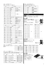
Address number
Set the address number using the
address setting switch (SW1) and No.4 of
the function setting switch (SW2).
Factory setting:
SW1: 0, SW2-No.4: OFF
(address number 0)
Address number
setting switch (SW1)
Function setting
switch (SW2-No.4)
Address
number
SW1
SW2-No.4
Address
number
SW1
SW2-No.4
0 0
16 0
1 1
17 1
2 2
18 2
3 3
19 3
4 4
20 4
5 5
21 5
6 6
22 6
7 7
23 7
8 8
24 8
9 9
25 9
10 A
26 A
11 B
27 B
12 C
28 C
13 D
29 D
14 E
30 E
15 F
OFF
31 F
ON
Baud rate
Set the baud rate using Nos. 1 to 3 of the
function setting switch (SW2) to.
Factory setting:
All OFF (9600 bps)
Function setting
switches
(SW2-Nos.1 to 3)
Baud rate (bps)
SW2-No.3
SW2-No.2
SW2-No.1
9600 OFF
OFF
OFF
19200 OFF
OFF ON
38400 OFF ON OFF
57600 OFF ON ON
115,200 ON OFF OFF
250,000 ON OFF ON
312,500 ON ON OFF
625,000 ON ON ON
Terminal resistor
Set the terminal resistor for RS-485
communication (120
Ω
) using the
terminal resistor setting switch (SW3).
Factory setting:
OFF (terminal resistor disabled)
ON
OFF
Terminal resistor
setting switch (SW3)
SW3
Terminal resistor (120
Ω
)
OFF Disabled
ON Enabled
Safety precautions
The precautions described below are intended to prevent danger or injury to the
user and other personnel through safe, correct use of the product. Use the
product only after carefully reading and fully understanding these instructions.
Warning
Handling the product without observing the instructions that accompany a
“Warning” symbol may result in serious injury or death.
General
•
Do not use the product in explosive or corrosive environments, in the presence
of flammable gases, locations subjected to splashing water, or near
combustibles. Doing so may result in fire, electric shock or injury.
•
Assign qualified personnel the task of installing, wiring, operating/controlling,
inspecting and troubleshooting the product. Failure to do so may result in fire,
electric shock or injury.
•
The motor will lose its holding torque when the power supply or motor
excitation turned off. If this product is used in an lifting application, be sure to
provide a measure for the position retention of moving parts. Failure to provide
such a measure may cause the moving parts to fall, resulting in injury or
damage to the equipment.
•
With certain types of alarms (protective functions), the motor may stop when
the alarm generates and the holding torque will be lost as a result. This will
result in injury or damage to equipment.
•
When the alarm is generated, first remove the cause and then clear the alarm.
Continuing the operation without removing the cause of the problem may
cause malfunction of the motor and driver, leading to injury or damage to
equipment.


