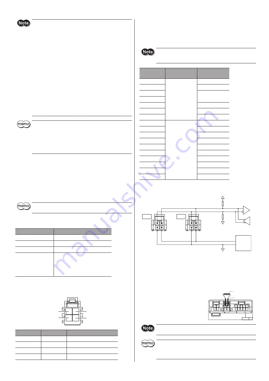
5
y
When connecting a power supply to multiple drivers in a daisy
chain, make sure that the total input current of the drivers is 6.5 A or
less. Exceeding 6.5 A may cause damage to the driver.
y
Connect the connectors securely. Insecure connections may cause
malfunction or damage to the motor or driver.
y
When connecting the connection cable, secure the cable so that no
load is applied to the CN1 to CN3 connectors. Applying a load to the
connector may result in a connection failure, and the driver may not
operate properly.
y
Keep 0.5 m (1.6 ft.) or less for the wiring distance between the motor
and driver. To extend more than 0.5 m (1.6 ft.) may result in increase
of the electrical noise emitted from the driver.
y
Keep 5 m (16.4 ft.) or less for the total wiring distance (*) of the
power/communication cable. To extend more than 5 m (16.4 ft.)
causes the driver to be affected easily by electrical noise.
* The total wiring distance refers to a wiring distance from the power
supply or the host controller, whichever the length of the cable
connected to the CN1 connector is longer, to the driver located at
the end. In the figure of the connection example, the total wiring
distance is from the host controller to the CN1 connector of the third
driver.
y
Before connecting or disconnecting the connector, turn off the main
power supply of the driver, and check the PWR/ALM LED has been
turned off.
y
When disconnecting the connector, pull off while pressing the latch
on the connector.
y
Connect GND of the power supply and GND of RS-485
communication to the same ground.
Connecting the main power supply, RS-485
communication, and termination resistor
(CN1, CN2)
Connect the main power supply and the RS-485 communication signal to
CN1 or CN2. When multiple drivers are used, they can be connected in a daisy
chain using CN1 or CN2. Power/communication cables are also available in
our products. Refer to p.8 for details.
The CN1 connector and CN2 connector are not electrically insulated.
You can connect either of the two connectors.
z
Applicable connector
Type
Model
Connector housing
105308-1204 (Molex Incorporated)
Contact
105300-2200 (Molex Incorporated)
Designated crimping tool 63827-5600 (Molex Incorporated)
Applicable lead wire
y
AWG22 to 20 (0.3 to 0.5 mm
2
)
y
Outer sheath diameter:
ø1.3 to 1.55 mm (0.05 to 0.06 in.)
y
Stripping length of wire insulation:
2.5 to 3.5 mm (0.1 to 0.14 in.)
z
Pin assignment
The figure shows the view from the contact insertion side.
1
3
2
4
Pin number
Signal name
Description
1
TR+
RS-485 communication signal (+)
2
TR−
RS-485 communication signal (−)
3
VIN
+24 VDC/+48 VDC
4
GND
Power supply GND
z
Power supply current capacity
The power supply current capacity varies depending on the product to be
combined.
When using the
EAS
Series, the
EAC
Series, and the
EZS
Series, check with
reference to the equipped motor model name.
When connecting a power supply to multiple drivers in a daisy chain,
make sure that the total input current of the drivers is 6.5 A or less.
Exceeding 6.5 A may cause damage to the driver.
Model
Input power supply
voltage
Power supply
current capacity
AZM14
24 VDC±5 %
0.4 A or more
AZM15
0.5 A or more
AZM24
1.4 A or more
AZM26
DGM60
1.4 A or more
DR28
1.3 A or more
EH4
1.4 A or more
AZM46
24 VDC±5 %
48 VDC±5 %
1.6 A or more
AZM48
2.1 A or more
AZM66
3.7 A or more
AZM69
3.5 A or more
DGB85
1.6 A or more
DGB130
3.7 A or more
DGM85
1.6 A or more
DGM130
3.7 A or more
DRSM42
1.5 A or more
DRSM60
2.6 A or more
z
Internal input circuit
100 kΩ
100 kΩ
0 V
Motor
Driver
Circuit
0 V
TR+
VIN
TR−
GND
+5 V
TR+
VIN
TR−
GND
CN2
CN1
z
Connecting the termination resistor
Connect a resistor between the TR+ terminal and the TR− terminal of CN1 or
CN2 for a driver located the farthest away (positioned at the end) from the
host controller.
Connecting method
1. Connect the lead wires to the resistor.
2. Connect the lead wires between the
TR+ terminal and the TR− terminal of
CN1 or CN2.
Resistor
Lead wires
Be sure to connect a resistor between the TR+ terminal and the TR−
terminal. Incorrect connection may cause damage to the resistor.
y
For a resistor, use a metal film resistor of 120 Ω, 1/2 W or more.
y
Do not crimp a resistor directly to the contacts. The contacts are
designed on the assumption that the stranded wire is crimped. The
resistor cannot be crimped sufficiently due to a single wire.


