


H-2386
1-800-295-5510
24
09.09/WE
ORGAPACK OR-T 400
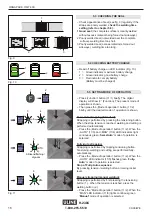
Fig. 19
1
3
4
2
5
Fig. 20
2
1
Fig. 21
3
2
1
6
4
5
7
PREVENTIVE/CORRECTIVE MAINTENANCE
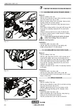
7.1 CLEANING/REPLACING TENSION WHEEL
Removal
– Remove battery from tool.
– Remove four cylinder screws (19/4) and remove strap
stop rear (19/5) and cover (19/3).
– Remove tension wheel (19/1) carefully. Remove ball
bearing (19/2) from tension wheel.
– Clean the tension wheel with compressed air (wear
goggles).
– If the tension wheel teeth are covered with heavy dirt,
they must be carefully cleaned with the wire brush
supplied.
– Check tension wheel for worn teeth. If a few teeth
are broken, replace tension wheel (observe rotating
direction, see arrow)
The tension wheel must not be cleaned
while it is rotating. There is a risk of
breaking teeth!
Installation
– Install the parts in reverse order.
– Grease gear teeth of tension wheel lightly with
Klüber grease GBU Y 131 (Microlube).
7.2 CLEANING/REPLACING TOOTH PLATE
Removal
– Remove battery from tool.
– Remove pan head screw (20/1). Lift the rocker lever
towards the handle and remove tooth plate (20/2).
– Clean tooth plate with compressed air (wear goggles).
– If the tooth plate teeth are covered with heavy dirt,
they must be carefully cleaned with the wire brush
supplied or a sharp tool.
– Check tooth plate for worn teeth, if necessary replace
tooth plate.
Installation
– Install the parts in reverse order.
– Secure pan head screw (20/1) with Loctite 222.
– The tooth plate (20/2) must be seated so it can move
freely in the rocker.
7.3 REPLACING KNIFE
Removal
– Remove battery from tool.
– Remove four cylinder screws (21/2) and remove strap
stop rear (21/3) and cover (21/1).
– Release panhead screw (21/4) and remove knife
(21/6) with
fl
anged bushing (21/5). Replace knife.
Installation
– Install the parts in reverse order.
– Before installing knife, check that the compressing
spring on top of knife is still mounted.
– Secure panhead screw (21/4) with Loctite 222.


