background image

5.

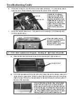
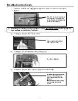
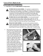
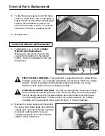
To test the power supply, touch the metal 
shaft of a screwdriver, with an insulated or
plastic handle, to one of the contacts while
keeping the screwdriver tip about 1/8" 
away from the other contact.  You should 
see an arc and hear a snapping sound.

6.

Reverse step 1.

Transformer Removal and Replacement

1.

Follow steps 1, 2, 3, and 6 of 

Motor 

Removal and Replacement.  
Remove two #6 screws and nuts that 
secure the transformer to the cabinet 
bottom.  Save for installment of the new 
transformer.

HIGH VOLTAGE WARNING - This equipment is supplied with line voltage from a 
standard wall socket.  Use standard precautions in working on it with line voltage 
applied.  Failure to practice normal electrical safety precautions can cause 
electrical shock, personal injury or property damage.

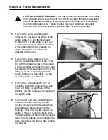
ROTATING ELEMENT WARNING - Unit has a rotating blower wheel and cooling 
fan to circulate air and keep the unit cool.  When servicing the unit and repairing 
the unit always insure that you keep objects and internal electrical wiring away 
from the rotating elements.  Failure to allow for proper clearance  for rotating 
members can cause electric shock, personal injury or property damage.

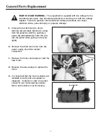
2.

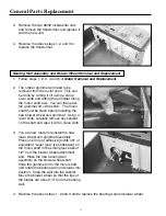
Remove the power supply and disconnect 
the yellow low voltage leads and white line
voltage lead.  Remove the black input line 
to selector switch position 4 using a 
straightened paper clip inserted into the 
selector switch connection.

21

General Parts Replacement

Summary of Contents for 447628

Page 1: ...S I M P L Y A M A Z I N G Service Manual Table Top Air Cleaner Super Air 5 Air 6 Model 447628 4478801 REV I Please disregard all earlier versions...

Page 2: ...ervicing Tools Required Multimeter Fluke Model 8024 B High Voltage Probe Fluke Model 80K 40 2 Flat Blade Screwdriver 2 Phillips Drive Screwdriver Diagonal Wire Cutters Wire nuts Needlenose Pliers Gene...

Page 3: ...ceive a positive electrical charge as they pass through the ionizing section The positive charged particles then enter the collecting section which uses a series of alternately charged aluminum plates...

Page 4: ...gative ion generator tip with a alcohol and a cotton swab 7 Clean the dirt and grime from the motor shaft using a soft cloth 8 Squirt a few drops of machine oil 3 in 1 type oil not WD 40 type oil in t...

Page 5: ...unit b With the top removed depress the interlock switch with a plastic handle screwdriver to test operation c If the motor and blower operate then the problem is that the interlock switch is not enga...

Page 6: ...erly seated in the bracket or is the bracket broken or distorted The switch is held in position by a bracket that allows the switch to be snapped between two locator ribs on the bracket 5 Are the wire...

Page 7: ...k for carbon paths or tracks on the cell ends If the switch plate cover is not secure it will prevent the top from engaging the interlock switch Insure that the cover is in position If the cell has lo...

Page 8: ...ssed The voltage should measure from 5 5 KVDC to 7 0 KVDC An alternate method to check voltage is by using a plastic handled screwdriver to short the high voltage contacts and observe a spark Option 2...

Page 9: ...to try to spin the blower wheel c Turn the unit over and check for signs of distortion in the cabinet bottom beneath the motor that might prevent the blower from spinning The stripper is held in posi...

Page 10: ...o remedy this a Clean the dirt and grime from the motor shaft using a soft cloth b Squirt a few drops of lubricating oil 3 in 1 type oil not WD 40 type oil in the slot on the shaft to lubricate the be...

Page 11: ...cket normally indicates motor overheating The motor should be replaced Insure that the isolator pads are in position Replace if the motor moved while being held in place with mounting bracket The outb...

Page 12: ...ove the cell and wash with warm soapy water Dry completely before re installing c If there are bent cell plates d If the cell is improperly installed in the unit e If the cell contacts are broken or l...

Page 13: ...present the ionizer is OK b If voltage is not present check HV power supply c If voltage is present at HV power supply but not the needle Clean needle with alcohol and a cotton swab See above diagram...

Page 14: ...__________________________ _____________________________________________________________________________ _____________________________________________________________________________ _________________...

Page 15: ...and Blower Wheel Removal and Replacement page 22 Led Assembly Removal and Replacement page 23 Cell Assembly Removal and Replacement page 23 Ionizer Needle Removal and Replacement page 23 Fan Blade Re...

Page 16: ...the bearing wall locator seat and then remove the stripper 4 Flip the unit onto its side with the bearing wall up and release the two locking tabs for the bearing wall assembly by using a regular scre...

Page 17: ...hed to the motor 6 Remove the power supply cover by placing a screwdriver blade in the cover slot with the blade inserted on the blower wheel side of the slot Catch the tan snap tab and twist the scre...

Page 18: ...black terminal 1 wires from the selector switch by pushing a paper clip straightened under the wire into the switch while pulling on the wire lightly 10 Remove the white motor wire from the power supp...

Page 19: ...age INSULATOR BOARD WARNING The unit has been designed with special insulator and isolator spacer boards that must be in position These boards are made of a special insulator material and must be in p...

Page 20: ...ternal electrical wiring away from the rotating elements Failure to allow for proper clearance for rotating members can cause electric shock personal injury or property damage 4 The power supply cover...

Page 21: ...n working on it with line voltage applied Failure to practice normal electrical safety precautions can cause electrical shock personal injury or property damage ROTATING ELEMENT WARNING Unit has a rot...

Page 22: ...must be clean before installing the new blower wheel and grommet Using a razor knife carefully remove any sealant on the shaft and wipe it with a clean cloth 3 You are now ready to reinstall the new...

Page 23: ...ce with a new cell 3 Reverse the above step 1 to replace the cell Ionizer Needle Removal and Replacement 1 Follow steps 1 3 and 6 of Motor Removal and Replacement EXTREME HIGH VOLTAGE WARNING This equ...

Page 24: ...3 and 6 of Motor Removal and Replacement ROTATING ELEMENT WARNING Unit has a rotating blower wheel and cooling fan to circulate air and keep the unit cool When servicing the unit and repairing the un...

Page 25: ...OP GRAY 1 12 442415 101 COLLECTOR CELL 1 13 142475 001 ION NEEDLE ASSEMBLY 1 14 342228 001 STRIPPER 1 15 342227 001 MOTOR MOUNTING BRACKET 1 16 136483 001 DRIVE GROMMET 1 17 342402 251 HV POWER SUPPLY...

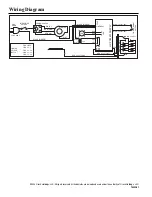
Page 26: ...RN RED BLUE 242477 035 ION COLL CELL POWER BOOST SWITCH BLUE 242477 035 CONTACT WALL GRN GRN BLACK RIBBED BRN MED RED LO BLACK RIBBED 120V 60HZ POWER SWITCH OUTPUT POS 1 OFF POS 2 L 1 POS 3 L 1 4 POS...

Page 27: ...__________________________ _____________________________________________________________________________ _____________________________________________________________________________ _________________...

Page 28: ...2004 Oreck Holdings LLC All rights reserved All trademarks are owned and used under the authority of Oreck Holdings LLC 75422 01 REV I 08 04 R 7693 R 7695...

Reviews: