


6
Fitting and maintenance instructions HRC 300/400 4B(P/RH)
3.5 Placing the heat recovery module
After fitting all the ducts at the mounting frame, and after fitting
the condensate discharge, the “heart” of the unit can now be
installed. Take the heat recovery module from the carton and
push it from the front into the mounting frame.
Push the unit fully to the back and secure by turning the handles
at the bottom 180°.
Figure 6: Placing the heat recovery module of the HRC
After positioning the heat recovery module, the dip switches
can be adjusted to give the desired air volume. (See § 3.9)
Ensure that the filters are correctly located.
3.6 Replacing the cover
After the heat recovery module is fixed in place the cover
can be attached. Offer up the cover with its front pointing
downwards. Hook the two brackets on the lower part of the
cover into the slots in the mounting frame. Now you can fix
the upper side of the cover at the upper side of the mounting
frame with the two screws provided. If it is difficult to push
the cover totally against the unit open the flap in the cover.
After closing the cover (and flap) the unit can be connected
to the power supply.
3.7 Electrical connections
3.7.1 HRC with 4 core and earth cable
The electric installation must comply with the local regulations.
3.7.2 HRC with wireless remote control
The electric installation must comply with the local regulations.
3.7.3 Speed control with 4 core and earth cable (BP model only)
The unit requires a power supply of 230 Volt (terminal L3 and N).
The speed control takes place by means of a 3-speed switch and
utilising 4 core and earth cabling to the unit.
For the correct wiring diagram see § 5.1.
3.7.4 Speed control with a wireless remote control
(BRH model only)
The HRC 300/400 BRH is delivered prewired. The unit must be
connected to 230V~50Hz supply by means of a 3A fused spur.
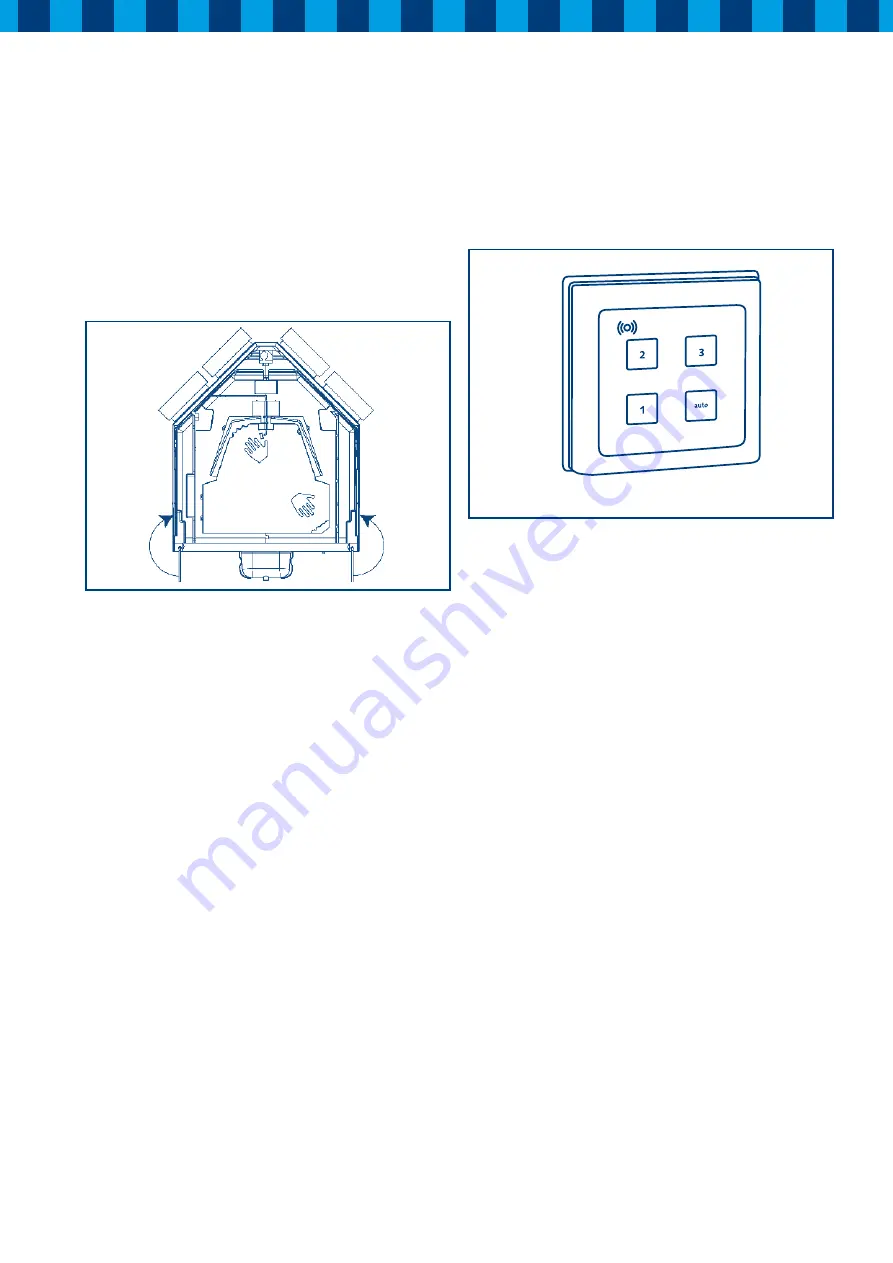
Figure 7: Wireless remote control
See § 5.4.2 for settings of the wireless remote controller.
3
= High
2
= Middle
1
= Low
Auto
= No function


