background image

Attach the CMA to the Server

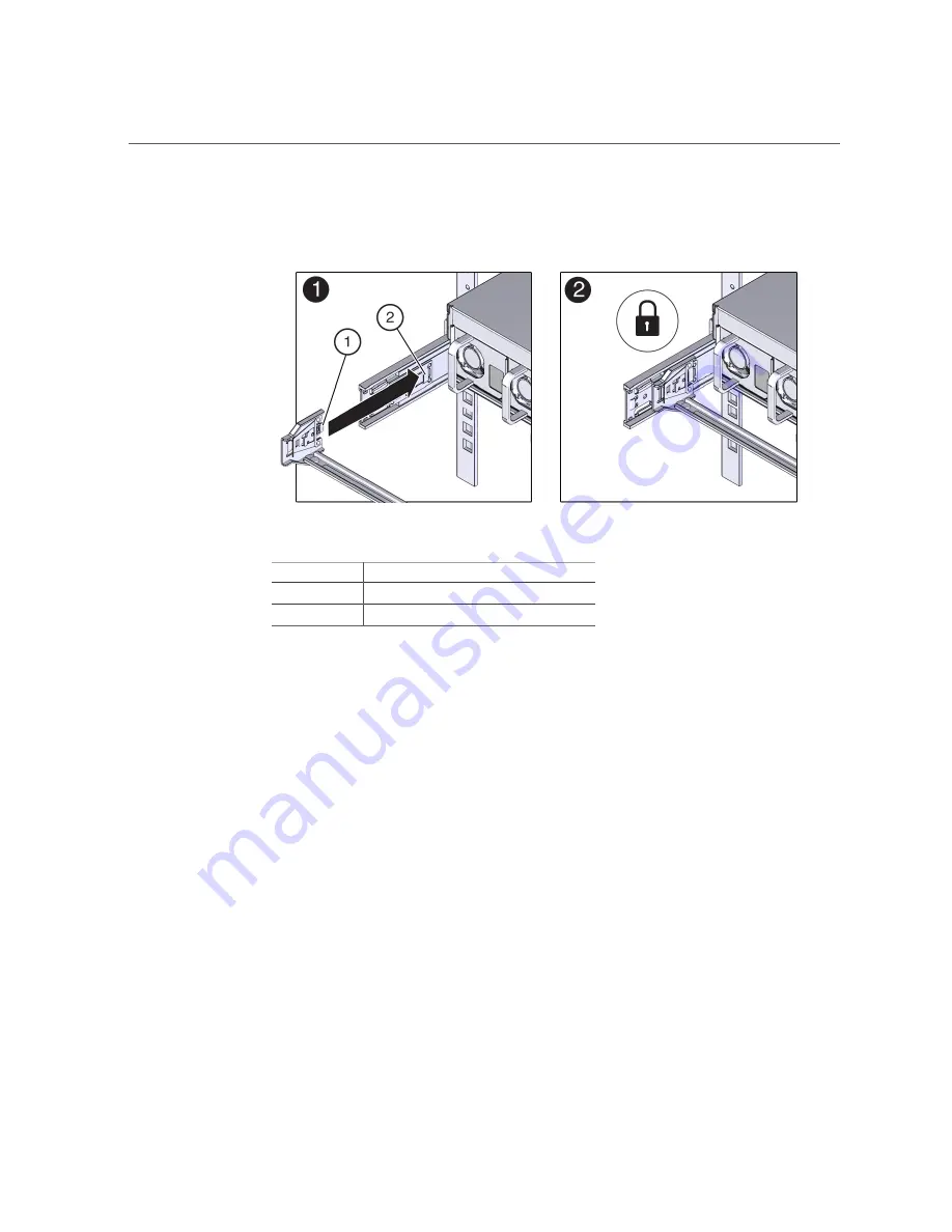
The connector A tab goes into the slide rail's front slot (panel 1).

No.

Description

1

Connector A tab

2

Left slide rail front slot

b.   

Gently tug on the right side of the front slide bar to verify that connector A is

properly seated.

5.

Install the CMA's connector B into the right slide rail.

a.   

Insert the CMA's connector B into the front slot on the right slide rail until it

locks into place with an audible click (panels 1 and 2).

The connector B tab goes into the slide rail's front slot (panel 1).

42

SPARC T8-1 Server Installation Guide • June 2019

Summary of Contents for SPARC T8-1

Page 1: ...SPARC T8 1 Server Installation Guide Part No E80507 03 June 2019 ...

Page 2: ......

Page 3: ...formation management applications It is not developed or intended for use in any inherently dangerous applications including applications that may create a risk of personal injury If you use this software or hardware in dangerous applications then you shall be responsible to take all appropriate fail safe backup redundancy and other measures to ensure its safe use Oracle Corporation and its affili...

Page 4: ...n des informations Ce logiciel ou matériel n est pas conçu ni n est destiné à être utilisé dans des applications à risque notamment dans des applications pouvant causer un risque de dommages corporels Si vous utilisez ce logiciel ou ce matériel dans le cadre d applications dangereuses il est de votre responsabilité de prendre toutes les mesures de secours de sauvegarde de redondance et autres mesu...

Page 5: ...ts 13 Preparing for Installation 15 Shipping Kit 15 Handling Precautions 17 ESD Precautions 17 Tools Needed for Installation 18 Specifications 19 Physical Specifications 19 Electrical Specifications 20 Environmental Specifications 21 Airflow Precautions 22 Installing the Server 25 Optional Components 25 Rack Compatibility 26 Rack Cautions 27 Stabilize the Rack 28 Install the Rackmount Hardware 29 ...

Page 6: ...Port 56 NET MGT Port 56 Gigabit Ethernet Ports 57 VGA Port 58 SAS Ports 58 Secure Cables to the CMA 60 Power on the System for the First Time 61 Installing the OS 62 Configure the Preinstalled OS 63 Reach a State to Install a Fresh OS Oracle ILOM CLI 63 Reach a State to Install a Fresh OS Oracle ILOM Web Interface 65 Oracle Solaris OS Configuration Parameters 67 Assign a Static IP Address to the N...

Page 7: ...d knowledge Experience with the Oracle Solaris OS troubleshooting and replacing hardware Product Documentation Library Documentation and resources for this product and related products are available at http www oracle com goto t8 1 docs Feedback Provide feedback about this documentation at http www oracle com goto docfeedback Using This Documentation 7 ...

Page 8: ...8 SPARC T8 1 Server Installation Guide June 2019 ...

Page 9: ...he First Time on page 51 Installation Task Overview Perform these tasks to install and configure the server Step Description Links 1 Review the Product Notes for any late breaking news about the server SPARC T8 Series Servers Product Notes 2 Review the server features specifications and site requirements Server Overview on page 10 Specifications on page 19 3 Confirm that you received all of the it...

Page 10: ...management cables to the server Connect Cables on page 51 9 Connect the power cords to the server configure the Oracle ILOM on the SP power on the server for the first time and set up the operating system Powering On the Server for the First Time on page 51 Related Information SPARC T8 Series Servers Product Notes SPARC T8 1 Server Safety and Compliance Guide SPARC T8 Series Servers Administration...

Page 11: ... Storage devices Eight 2 5 inch drive bays accessible through the front panel USB ports Two external USB 3 0 ports rear panel Two external USB 2 0 ports front panel Video port One high density DB 15 video port rear Ethernet ports Four 10GbE 100 Mbps 1 Gbps 10 Gbps RJ 45 based ports on the rear panel Power supplies Two hot swappable 1 1 AC 1200W power supplies Cooling fans Four hot swappable redund...

Page 12: ...Server Locate indicator and button white 2 System Fault Service Required LED amber 3 System OK indicator green 4 Power button 5 SP OK indicator green 6 Fan Fault LED amber 7 PS fault LED amber 8 Overtemperature LED amber 9 USB 2 0 connectors 2 10 Server serial number 11 Drive 1 12 Drive 0 12 SPARC T8 1 Server Installation Guide June 2019 ...

Page 13: ... drive 3 17 Drive 6 18 Drive 7 Related Information Server Overview on page 10 Rear Panel Components on page 13 Connect Cables on page 51 Rear Panel Components Note You must follow the proper sequence when connecting cables to the server Do not connect the power cords until all data cables have been connected Understanding the Server 13 ...

Page 14: ...k port 8 PCIe slot 4 9 PCIe slot 5 10 PCIe slot 6 11 Network 10GbE 100 Mbps 1 Gbps 10 Gbps ports NET 0 to NET 3 12 USB 3 0 connectors 2 13 NET MGT RJ 45 network port Related Information Front Panel Components on page 12 Connect Cables on page 51 Attach the CMA to the Server on page 41 Secure Cables to the CMA on page 60 14 SPARC T8 1 Server Installation Guide June 2019 ...

Page 15: ...hat you have the correct tools Tools Needed for Installation on page 18 Related Information Installing the Server on page 25 Connect Cables on page 51 Powering On the Server for the First Time on page 51 Shipping Kit Note When you receive your server place it in the environment where you will install it Leave it in its shipping crate at its final destination for 24 hours This resting period preven...

Page 16: ...r cords Note The shipping kit might also contain PCIe fillers that were removed from the server when PCIe cards were installed in the factory Save these PCIe fillers and use them to cover PCIe slots when cards are removed from the server Related Information Server Overview on page 10 Preparing for Installation on page 15 16 SPARC T8 1 Server Installation Guide June 2019 ...

Page 17: ...pleting a two person procedure always communicate your intentions clearly before during and after each step to minimize confusion Related Information Physical Specifications on page 19 Installing the Server on page 25 SPARC T8 1 Server Getting Started Guide ESD Precautions Electronic equipment is susceptible to damage by static electricity Use a grounded antistatic wrist strap foot strap or equiva...

Page 18: ...g strap connected to a metal surface on the chassis when you work on server components Related Information Handling Precautions on page 17 Tools Needed for Installation No 2 Phillips screwdriver ESD mat and grounding strap In addition you must provide a system console device such as one of the following ASCII terminal Workstation Terminal server Patch panel connected to a terminal server Related I...

Page 19: ...r Overview on page 10 Shipping Kit on page 15 Identifying Ports on page 55 Physical Specifications Description U S Metric Rack units 2U 2U Height 3 45 in 87 6 mm Width 17 5 in 445 mm Depth 29 in 737 mm Weight without rackmount kit 57 5 lb 26 08 kg Minimum service clearance front 48 5 in 1232 mm Minimum service clearance rear 36 in 914 4 mm Minimum airflow clearance front 2 in 50 8 mm Minimum airfl...

Page 20: ...r cord 5 7 A Actual amperage draw may exceed rating by no more than 10 Maximum operating input power at 200 VAC 1300W Maximum standby power 20W Maximum heat dissipation 4456 BTU hr 4702 KJ hr The maximum operating input current values are based on P V 0 90 where P max operating input power V input voltage Example 620W 120 0 90 6 89A You can use this equation to calculate your maximum operating cur...

Page 21: ... maximum temperature above 3000 ft 900m 1 8 F 1000 ft 1 C 300m Relative humidity 10 to 80 at 81 F 10 to 80 at 27 C Up to 85 at 100 F Up to 85 at 38 C Maximum wet bulb noncondensing Altitude 0 to 9840 ft at 95 F 0 m to 3000m at 40 C Up to 39 370 ft Up to 12 000m Except in China markets where regulations might limit installations to a maximum altitude of 2km TABLE 2 Shock and Vibration Specification...

Page 22: ...server Follow these guidelines to ensure unrestricted airflow in the server Adhere to the minimum airflow clearance specifications See Physical Specifications on page 19 Install the server so the front faces the cool aisle and the rear faces the warm aisle Do not direct warm air into the server Prevent recirculation of air within a rack or cabinet When servicing server internal components ensure t...

Page 23: ...Airflow Precautions Physical Specifications on page 19 Electrical Specifications on page 20 Environmental Specifications on page 21 Specifications 23 ...

Page 24: ...24 SPARC T8 1 Server Installation Guide June 2019 ...

Page 25: ...ure that the rack does not tip when the server is installed Stabilize the Rack on page 28 5 Prepare the slide rails mounting brackets and slide rail assemblies for server installation Install the Rackmount Hardware on page 29 Attach Slide Rail Assemblies to the Rack on page 31 6 Install the server in the rack Install the Server Into the Slide Rail Assemblies on page 35 7 Optional Install the CMA A...

Page 26: ...standards Item Requirement Structure 4 post rack mounting at both front and rear 2 post racks are not compatible Rack horizontal opening and unit vertical pitch Conforms to ANSI EIA 310 D 1992 or IEC 60927 standards Rack rail mounting hole sizes Only 9 5 mm square hole and M6 round mounting holes are supported All other sizes including 7 2 mm M5 or 10 32 mounting holes are not supported Distance b...

Page 27: ...mperature Tma specified for the server Caution Reduced Air Flow Install the equipment in a rack so that the amount of air flow is adequate for the safe operation of the equipment Caution Mechanical Loading Mount the equipment in the rack so that the weight is distributed evenly A hazardous condition can exist with uneven mechanical loading Caution Circuit Overloading Do not overload the power supp...

Page 28: ...s before installing the server Refer to the rack documentation for detailed instructions for the following steps 1 Read the rack cautions and stabilize the rack See Rack Cautions on page 27 2 Open and remove the front and rear doors from the rack 3 To prevent the rack cabinet from tipping during the installation stabilize the cabinet using all antitilt mechanisms provided 4 If there are leveling f...

Page 29: ...the slide rail assemblies before installation 1 Unpack the slide rails The rackmount kit contains two slide rails two mounting brackets and optional securing screws Note Refer to the rackmount kit installation card for simplified instructions about installing your server into a 4 post rack using the slide rail and CMA options No Description 1 Slide rails 2 Mounting brackets 3 Four M4 x 5 fine pitc...

Page 30: ...enings on the mounting bracket are aligned with the five locating pins on the side of the chassis No Description 1 Server front 2 Slide rail lock 3 Mounting bracket 4 Mounting bracket clip 3 With the heads of the five chassis locating pins protruding through the five keyhole openings in the mounting bracket pull the mounting bracket toward 30 SPARC T8 1 Server Installation Guide June 2019 ...

Page 31: ...o the Rack on page 31 Related Information Attach Slide Rail Assemblies to the Rack on page 31 Attach Slide Rail Assemblies to the Rack Use the rackmount installation card to identify the correct mounting holes for the slide rails Note Load the rack from bottom to top 1 Unpack the mounting brackets and installation card from the rackmount kit See Install the Rackmount Hardware on page 29 2 Ensure t...

Page 32: ...f the card corresponds to the bottom edge of the server Measure up from the bottom of the installation card 4 Mark the mounting holes for the front slide rails 5 Mark the mounting holes for the rear slide rails 32 SPARC T8 1 Server Installation Guide June 2019 ...

Page 33: ...ail Assemblies to the Rack 6 Orient the slide rail assembly so that the ball bearing track is forward and locked in place No Description 1 Slide rail 2 Ball bearing track 3 Locking mechanism Installing the Server 33 ...

Page 34: ...ble click 8 Align the front of the slide rail assembly against the outside of the front rack rail and push until the assembly locks into place with an audible click 9 Repeat this procedure to attach the slide rail assembly to the other side of the rack 10 If available extend the antitip legs or antitilt bar at the bottom of the rack Refer to the documentation for the rack for instructions 34 SPARC...

Page 35: ...of two people because of the weight of the server Attempting this procedure alone could result in equipment damage or personal injury Caution Always load equipment into a rack from the bottom up so that the rack does not become top heavy and tip over Extend the rack s antitilt bar to prevent the rack from tipping during equipment installation 1 Attach the rackmount hardware to the server and the r...

Page 36: ...ches or 30 cm No Description 1 Inserting mounting bracket into slide rail 2 Slide rail release lever 5 Simultaneously pull down and hold the slide rail release levers on each mounting bracket while you push the server into the rack Continue pushing the server into the rack until the slide rail locks on the front of the mounting brackets engage the slide rail assemblies 36 SPARC T8 1 Server Install...

Page 37: ...he slide rail assembly to the rack with screws insert the M4 mounting screws that are provided with the rail kit through the front left and right slide rail brackets and rack posts 7 Optional Attach the CMA See Prepare the CMA for Installation on page 38 If you are not using the CMA see Verify Operation of Slide Rails and CMA on page 47 Related Information Prepare the CMA for Installation on page ...

Page 38: ...installation at the rear of the server 1 Install the server in the rack before attaching the CMA See Install the Server Into the Slide Rail Assemblies on page 35 2 Unpack the CMA The following figure shows the CMA components No Description 1 Connector A 2 Front slide bar 38 SPARC T8 1 Server Installation Guide June 2019 ...

Page 39: ...ers Note The CMA ships with three flat cable covers installed Before installing the CMA you must replace the flat cable covers with the round cable covers If the round cable covers are already on the CMA skip the next step 4 If needed Remove the flat cable covers and install the round cable covers To remove the flat cable covers and install the round cable covers perform these steps for each cable...

Page 40: ...off the hinge panel 3 c One at a time position each round cable cover horizontally over the hinges and align the hinge connectors with the hinges d Using your thumb apply downward pressure on each hinge connector to snap the hinge connector into place e Swing the cable covers down and press down on the cable cover handle to lock them into the closed position 5 Ensure that the six Velcro straps are...

Page 41: ...re installed on the CMA 1 Prepare the CMA for installation on the server See Prepare the CMA for Installation on page 38 2 To make it easier to install the CMA extend the server approximately 13 cm 5 inches out of the front of the rack 3 Take the CMA to the back of the equipment rack and ensure that you have adequate room to work at the back of the server Note References to left or right in this p...

Page 42: ...side of the front slide bar to verify that connector A is properly seated 5 Install the CMA s connector B into the right slide rail a Insert the CMA s connector B into the front slot on the right slide rail until it locks into place with an audible click panels 1 and 2 The connector B tab goes into the slide rail s front slot panel 1 42 SPARC T8 1 Server Installation Guide June 2019 ...

Page 43: ...y tug on the right side of the front slide bar to verify that connector B is properly seated No Description 1 Connector B tab 2 Right slide rail front slot 6 Install the CMA s connector C into the right slide rail Installing the Server 43 ...

Page 44: ...panel 1 No Description 1 Connector C locking spring b Insert connector C into the right slide rail until it locks into place with an audible click panels 2 and 3 c Gently tug on the right side of the CMA s rear slide bar to verify that connector C is properly seated 7 Prepare the CMA s connector D for installation 44 SPARC T8 1 Server Installation Guide June 2019 ...

Page 45: ... s connector D into the left slide rail a While holding the slide rail latching bracket in place insert connector D and its associated slide rail latching bracket into the left slide rail until connector D locks into place with an audible click panels 1 and 2 Note When inserting connector D into the slide rail the preferred and easier method is to install connector D and the latching bracket as on...

Page 46: ... a green release tab This tab is used to release and remove the latching bracket so that you can remove connector D 10 Gently tug on the four CMA connection points to ensure that the CMA connectors are fully seated before you allow the CMA to hang by its own weight 11 Verify that the slide rails and CMA operate properly See Verify Operation of Slide Rails and CMA on page 47 Related Information Pre...

Page 47: ... to move the server in and out of the rack and one to observe the cables and CMA 1 Slowly pull the server out of the rack until the slide rails reach their stops 2 Inspect the attached cables for any binding or kinks 3 Verify that the CMA extends fully from the slide rails 4 Push the server back into the rack Installing the Server 47 ...

Page 48: ... The server slides in approximately 18 inches 46 cm and stop Verify that the cables and the CMA retract without binding before you continue b The second set of stops are the slide rail release buttons located near the front of each mounting bracket Simultaneously push both of the green slide rail release buttons and push the server completely into the rack until both slide rail locks engage 5 Adju...

Page 49: ...Verify Operation of Slide Rails and CMA Secure Cables to the CMA on page 60 Installing the Server 49 ...

Page 50: ...50 SPARC T8 1 Server Installation Guide June 2019 ...

Page 51: ...nsole Power on the System for the First Time on page 61 5 Configure the preinstalled OS or install a fresh OS Installing the OS on page 62 6 Optional Configure the NET MGT port to use a static IP address Assign a Static IP Address to the NET MGT Port on page 68 7 Optional Activate Oracle Auto Service Request for the server Oracle Auto Service Request Software Activation on page 70 Related Informat...

Page 52: ...crossovers given for each connector a Configure a terminal or terminal emulator with these settings 9600 baud 8 bits No parity 1 Stop bit No handshake A null modem configuration is needed meaning the transmit and receive signals are reversed crossed over for DTE to DTE communications You can use the supplied RJ 45 crossover adapters with a standard RJ 45 cable to achieve the null modem configurati...

Page 53: ...itch or hub The SP network management port is labeled NET MGT After the initial server configuration you can connect to the SP over an Ethernet network using this NET MGT port If your network uses a DHCP server to assign IP addresses the DHCP server assigns an IP address to this NET MGT port With this IP address you can connect to the SP using an SSH connection If your network does not use DHCP th...

Page 54: ...s connect the appropriate I O cables to their connectors Refer to the PCIe card documentation for specific instructions 5 Route the power cords from separate AC power sources to the server then connect the power cords to the power supplies When the power cords are connected the SP initializes and the power supply LEDs illuminate After a few minutes the SP login prompt is displayed on the terminal ...

Page 55: ...s on page 13 The USB ports support hot plugging You can connect and disconnect USB cables and peripheral devices while the server is running without affecting server operations Each USB 2 0 port supplies 5V output at 500 mA Each USB 3 0 port supplies 5V output at 900 mA Note You can connect up to 126 devices to each of the four USB controllers two ports in front two ports in the rear for a total o...

Page 56: ...nal Description 1 Request to Send 5 Ground 2 Data Terminal Ready 6 Receive Data 3 Transmit Data 7 Data Set Ready 4 Ground 8 Clear to Send NET MGT Port The NET MGT RJ 45 port located on the rear panel provides an optional Ethernet connection to the SP The NET MGT port is an optional connection to Oracle ILOM on the SP The SP NET MGT port uses an RJ 45 cable for a 1000BASE T connection auto negotiat...

Page 57: ...NET 3 can be accessed from the rear panel See Rear Panel Components on page 13 The Ethernet interfaces operate at 100 Mbps 1000 Mbps and 10000 Mbps Pin Signal Description Pin Signal Description 1 Transmit Receive Data 0 5 Transmit Receive Data 2 2 Transmit Receive Data 0 6 Transmit Receive Data 1 3 Transmit Receive Data 1 7 Transmit Receive Data 3 4 Transmit Receive Data 2 8 Transmit Receive Data ...

Page 58: ...or and the VGA port should not be over 6 meters Pin Signal Description Pin Signal Description 1 Red Video 9 KEY 2 Green Video 10 Sync Ground 3 Blue Video 11 Monitor ID Bit 1 4 Monitor ID Bit 2 12 VGA 12C Serial Data 5 Ground 13 Horizontal Sync 6 Red Ground 14 Vertical Sync 7 Green Ground 15 VGA 12C Serial Clock 8 Blue Ground SAS Ports The eight SAS connectors are located on the drive backplane ins...

Page 59: ...mate S8 Gnd Second mate S9 S10 S11 Gnd Second mate S12 S13 Back side signal S8 to S14 S14 Gnd Second mate P1 3 3V Not Supported P2 3 3V Not Supported P3 3 3V Not Supported P4 Gnd First mate P5 Gnd Second mate P6 Gnd Second mate P7 5 0V Pre charge second mate P8 5 0V P9 5 0V P10 Gnd Second mate P11 Reserved Should be grounded P12 Gnd First mate P13 12 0V Pre charge second mate P14 12 0V Power segme...

Page 60: ...rver cables secure them to the CMA if a CMA was installed 1 Attach the CMA to the server in the rack See Prepare the CMA for Installation on page 38 and Attach the CMA to the Server on page 41 2 Open the cable covers and straps on the CMA 3 Route the server cables through the CMA cable covers and straps 60 SPARC T8 1 Server Installation Guide June 2019 ...

Page 61: ...le ILOM To build a secure environment you must change the default password of the default Administrator account as soon as possible after your initial login to Oracle ILOM If you find this default Administrator account has already been changed contact your system administrator to obtain an Oracle ILOM user account with Administrator privileges For more information about the administration tasks su...

Page 62: ...ame c To return to displaying host output from the server initialization type start HOST console 5 Continue with the installation by installing the OS See Installing the OS on page 62 Related Information Connect Cables on page 51 Configure the Preinstalled OS on page 63 Reach a State to Install a Fresh OS Oracle ILOM CLI on page 63 Reach a State to Install a Fresh OS Oracle ILOM Web Interface on p...

Page 63: ...ow to respond to a particular value you can accept the default and make future changes when the Oracle Solaris OS is running See Oracle Solaris OS Configuration Parameters on page 67 for a description of the Oracle Solaris OS parameters you must provide during initial configuration 3 Log in to the server You can now enter Oracle Solaris OS commands at the prompt For more details refer to the Oracl...

Page 64: ...allation reset the host reset System Are you sure you want to reset System y n y Performing reset on System 4 Switch communication to the server host start HOST console Are you sure you want to start HOST console y n y Serial console started To stop type The server might take several minutes to complete POST and then the OpenBoot prompt ok is displayed 5 Boot from the appropriate boot media for yo...

Page 65: ... a Static IP Address to the NET MGT Port on page 68 Reach a State to Install a Fresh OS Oracle ILOM Web Interface If you do not plan to use the preinstalled OS use this procedure to prevent the server from booting from the preinstalled OS 1 Prepare the appropriate boot media according to your installation method There are many methods by which you can install the OS For example you can boot and in...

Page 66: ...e left navigation panel click on Host Management Power Control 6 Select Reset from the pull down menu and click Save 7 In the left navigation panel click on Remote Control Redirection 8 Select Use Serial Redirection and click Launch Remote Console As the host resets messages are displayed in the serial console The reset activity takes a few minutes to complete When the ok prompt is displayed conti...

Page 67: ...tic IP Address to the NET MGT Port on page 68 Oracle Solaris OS Configuration Parameters When configuring the Oracle Solaris OS you are prompted for the following configuration parameters For more information about these settings refer to the Oracle Solaris documentation Parameter Description Language Select a number from the displayed language list Locale Select a number from the displayed locale...

Page 68: ... the default date and time or change the values root Password Type the root password twice This password is for the superuser account for the Oracle Solaris OS on this server This password is not the SP password Related Information Oracle Solaris OS documentation Configure the Preinstalled OS on page 63 Reach a State to Install a Fresh OS Oracle ILOM CLI on page 63 Reach a State to Install a Fresh...

Page 69: ...SP network pendingipnetmask 255 255 255 0 Set pendingipnetmask to 255 255 255 0 This example uses 255 255 255 0 to set the netmask Your network environment subnet might require a different netmask Use a netmask number most appropriate to your environment 6 Verify that the parameters were set correctly This example shows parameters that have been set to convert a SP from a DHCP configuration to a s...

Page 70: ...ou have completed initial installation and Oracle Solaris configuration you can activate Oracle Auto Service Request Oracle ASR software for the server Oracle ASR software provides the ability to resolve problems faster by automatically opening service requests for Oracle s qualified server storage and Engineered System products when specific faults occur Parts are dispatched upon receipt of a ser...

Page 71: ...r ASR assets such as a new server To activate automated support for a server download software and find additional information at http www oracle com us support auto service request index html Some of resources available for Oracle ASR through that site are Oracle Auto Service Request Documentation http docs oracle com cd E37710_01 index htm How to Approve Pending ASR Assets In My Oracle Support D...

Page 72: ...72 SPARC T8 1 Server Installation Guide June 2019 ...

Page 73: ...unting bracket 41 securing cables 60 slide rail connector 41 configuring Oracle Solaris 67 cooling fans 10 CPU description 10 current specifications 20 D depth specification 19 DHCP servers 51 DIMM description 10 drives 10 E electrical specifications 20 elevation specification 21 environmental specifications 21 ESD precautions 17 Ethernet ports cabling 51 51 location 10 13 pinouts 57 sideband mana...

Page 74: ...lling a fresh OS Oracle ILOM CLI 63 installing a fresh OS Oracle ILOM web interface 65 Overtemperature LED location of 12 P PCIe cards location 10 slots 10 physical specifications 19 pinouts Ethernet ports 57 NET MGT port 56 SAS connector 58 SER MGT port 56 USB ports 55 video connector 58 Power button location of 12 power calculator 20 power cords cabling 51 power specifications 20 power supplies ...

Page 75: ...nd 68 sideband management 51 51 site planning specifications 19 slide rail lock 29 release 29 slide rail assemblies disassembling 29 installing 29 stops 47 SP Fault LED 12 specifications 19 acoustic 21 altitude 21 current 20 electrical 20 elevation 21 environmental 21 frequency 20 heat dissipation 20 humidity 21 physical 19 power 20 temperature 21 vibration 21 voltage 20 standby mode 51 status LED...

Page 76: ...76 SPARC T8 1 Server Installation Guide June 2019 ...

Reviews: