Operator
‘s Manual
optris
®
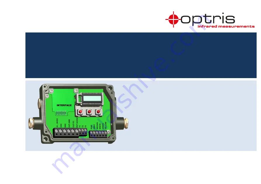
PROFIBUS
Interface for optris CT infrared thermometers
Page 1: ...Operator s Manual optris PROFIBUS Interface for optris CT infrared thermometers...
Page 2: ...Optris GmbH Ferdinand Buisson Str 14 13127 Berlin Germany Tel 49 30 500 197 0 Fax 49 30 500 197 10 E mail info optris global Internet www optris global...
Page 3: ...ription 6 1 2 Warranty 6 1 3 Scope of supply 7 2 Installation Interfaces 8 2 1 Setting PROFIBUS address at optris CT 9 2 2 Information regarding GSD file 9 2 3 Operation of optris CT with the PROFIBUS...
Page 4: ...2 1 Diagnosis during cyclic data transfer 14 4 3 Synchronization of sync and freeze 14 4 4 State of things within the master 14 4 5 State machinery within the slave 15 4 6 DP master class 1 and class...
Page 5: ...er 26 4 10 1 DP V1 interface 26 4 10 2 Data of the couple Slot_Number 0 27 4 10 3 Data for function modules 29 4 11 DP diagnosis 30 4 11 1 Identification oriented Diagnosis 30 4 11 2 Module status 31...
Page 6: ...ery date After the warranty is expired the manufacturer guarantees additional 6 months warranty for all repaired or substituted product components Warranty does not apply to damages which result from...
Page 7: ...General Information 7 1 3 Scope of supply PROFIBUS DP V1 interface M12 device socket Cable connection M12x1 5 2 screws M3x5 Software CD operators manual GSD file Brief instruction...
Page 8: ...which is right next to the display Push down the PROFIBUS DP V1 interface and adjust it with the supplied screws M3x5 within the electronic box Please connect the device socket with the screw terminal...
Page 9: ...th the UP and DOWN buttons this will be taken over after six seconds Then the optris CT has to be removed from the voltage for three seconds This procedure must always be carried out when a new slave...
Page 10: ...en LED on the Profibus DP V1 interface if the cover was removed from the optris CT open only for testing purposes 2 4 Data conversion The cyclic received data of the object temperature and the interna...
Page 11: ...5 V E 0 9 7 0 E Emissivity here 0 970 T 1 0 0 0 T Transmission ratio here 1 000 A 0 2 A Signal output average here 0 2 s P P Signal output maximum here inactive V V Signal output minimum here inactiv...
Page 12: ...he amount of calculations that the slave has to perform by receiving parameter and configuration data until it is ready for data exchange this may take several seconds The slave therefore has the foll...
Page 13: ...e diagnostics data is requested by the master with a SlaveDiag request telegram without data the slave sends the diagnostics data with a SlaveDiag response telegram The diagnostic data consists of the...
Page 14: ...input of the inputs freeze for several slaves When the sync command is used the slaves are first switched to the sync mode acknowledged in the diagnostics data then the IO data is exchanged sequential...
Page 15: ...PROFIBUS DP 15 4 5 State machinery within the slave...
Page 16: ...C2 connection differ in that the acyclic C1 connection is established with the DP startup of the cyclic DP operation From the state WAIT CFG of the slave acyclic DP V1 C1 read and write telegrams can...
Page 17: ...r no circumstances be exchanged otherwise the communication is disturbed Pin 2 transmits 5 VDC and Pin 4 transmits GND for the active terminator These may under no circumstances be used for other func...
Page 18: ...5 0 Publisher Mode is not supported 1 Publisher Mode is supported 3 0 WD Time Base 10ms 1 WD Time Base 1ms 1 6 0 DP V1 process alarm is not supported 1 DP V1 process alarm is supported 5 0 DP V1 Diagn...
Page 19: ...nel related diagnostics 1 0 Release module status 1 Disable module status 0 0 Release identifier related diagnostics 1 Disable identifier related diagnostics 8 0 0 Status alarm clear 1 Status alarm lo...
Page 20: ...20...
Page 21: ...re formed from the modules added in the DP configuration tool When attaching the modules the following rules must be observed each module is allowed to be plugged only once the sequence of the module...
Page 22: ...Byte Bit Data Description 0 0x0A Parameter data length 1 Slot number 2 0x01 Module identification 3 6 0 DP V0 Process alarm not supported 1 DP V0 Process alarm supported 4 5 Reserved 6 7 Maximum bound...
Page 23: ...temperature Byte Bit Data Description 0 0x0A Parameter data length 1 Slot number 2 0x02 Module identification 3 6 0 DP V0 Process alarm not supported 1 DP V0 Process alarm supported 4 5 Reserved 6 7...
Page 24: ...24 4 9 3 Module telegram Used for transferring the Optris special commands Data from Master Slave Byte Description 0 Handshake 1 Data0 2 Data1 3 Data2 4 Data3 5 Data4 6 Data5 7 Data6 8 Data7 9 Data8...
Page 25: ...h of telegram receive telegram F1hex Timeout no telegram received 1 Handshake 2 Data0 3 Data1 4 Data2 5 Data3 6 Data4 7 Data5 8 Data6 9 Data7 10 Data8 11 Data9 12 Data10 13 Data11 14 Data12 15 Data13...
Page 26: ...rPrmData Byte Bit Data Description 0 7 1 MSAC_C1 connection will be activated The MSAC_C2 connection can be used by a C2 master which then communicates only acyclically with the slave and has its own...
Page 27: ...ength Description 0 R W 10 Parameter Emissivity Transmission ratio Average time Hold time Signal threshold 1 R W 2 Emissivity 2 R W 2 Transmission ratio 3 R W 2 Averaging time 4 R W 2 Hold time 5 R W...
Page 28: ...28 R 21 Data0 Data1 Data2 Data3 Data4 Data5 Data6 Data7 Data8 Data9 Data10 Data11 Data12 Data13 Data14 Data15 Data16 Data17 Data18 Data19 Data20 255 R 64 I M data record 0...
Page 29: ...rved Byte2 Reserved Byte3 4 maximum boundary value Byte5 6 minimum boundary value 0x01 R 2 Byte0 1 Measurement value Internal sensing head temperature Index Access Data length Description 0x00 R W 7 M...
Page 30: ...nged diagnostic data automatically The device supports the following diagnosis Norm diagnosis Diagnosis alarm Identification orientated diagnosis Process alarm Module status 4 11 1 Identification orie...
Page 31: ...group and represents a detail of the identifier related diagnostics with regard to the configuration The module status begins after the identifier related diagnostics and comprises 5 bytes The module...
Page 32: ...ion about channel errors of modules and provide a detail of the identifier related diagnostics The channel related diagnostics starts after the module status The channel related diagnosis does not inf...
Page 33: ...ort circuit Channel_Diag 19 Box Temperature too high Channel_Diag 26 Error 10 Status alarm Channel_Diag 20 Error Statusbyte 24 Channel_Diag 21 Error Statusbyte 28 Channel_Diag 22 Sensing head Temperat...
Page 34: ...ation 0x03 0x00 0x01 Coming result 0x02 Leaving result 0x04 Error Bit 0 Assembly group disruption Bit 1 Internal error Bit 2 External error Bit 3 Channels 0x05 0x03 Number of channels 0x06 Bit 0 Diagn...
Page 35: ...ct Safety Directive 2001 95 EC EMC General Requirements EN 61326 1 2013 Basic requirements EN 61326 2 3 2013 Safety of measurement devices EN 61010 1 2010 This product is in conformity with Directive...
Page 36: ...optris PROFIBUS MA E2021 03 A...