-
14
-
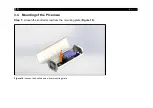
3.2 Installation (with visible camera) [hier Variante B]
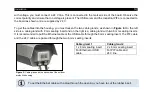
Connect the network cable to a PoE
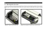
3.3 Mounting of the USB server
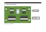
Insert the USB server at a slanted angle to the designated disk (
). If necessary, remove the clip from
the USB server (
) until the clip is locked into the bracket (
Figure 6:
Insertion of the USB server into the provided board
Figure 7:
USB server clip
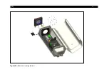
Figure 8:
USB server holding plate
Summary of Contents for Outdoor protective housing
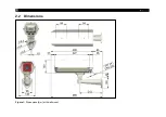
Page 8: ... 8 2 2 Dimensions Figure 1 Dimensions mm with wall mount ...
Page 9: ...Technical Data 9 Figure 2 Dimensions for wall mount ...
Page 26: ... 26 Figure 24 Remove air purge laminar ...
Page 32: ... 32 Appendix A Declaration of Conformity ...
Page 33: ......
Page 34: ...optris Outdoor protective housing MA E2022 10 A ...

