-
12
-
3 Installation
3.1 Electrical installation (w/o visible camera)
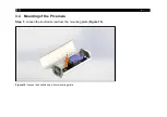
Loosen the two screws and open the outdoor protective housing, as shown in
Figure 4:
Opening the housing
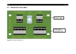
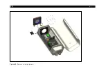
Inside the protective housing is the electronic circuit board, where all loads are connected (see
). The
heating element and the fan are already integrated and connected. To supply the outdoor protective housing
Summary of Contents for Outdoor protective housing
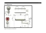
Page 8: ... 8 2 2 Dimensions Figure 1 Dimensions mm with wall mount ...
Page 9: ...Technical Data 9 Figure 2 Dimensions for wall mount ...
Page 26: ... 26 Figure 24 Remove air purge laminar ...
Page 32: ... 32 Appendix A Declaration of Conformity ...
Page 33: ......
Page 34: ...optris Outdoor protective housing MA E2022 10 A ...

