

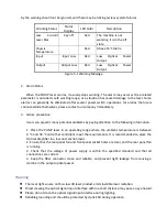


IP address
Menu#17 -IP GATEWAY
IP gateway
Menu#18 -IP MASK
Subnet Mask
3
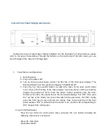
Menu Operation
A.
Key Settings
1> Switch the menu to the Laser Key State display page.
2> Press the “Enter” key and then press the “ESC” key, then press the “up” key or the
“Down” key to switch the switch state.
3> Press the “ESC” key to save and exit the settings.
B.
IP address Settings
1> Switch the menu to the IP address display page.
2> Press the “Enter” key and then press the “ESC” key to enter the IP setting state. At
this time, the cursor will flash. Press the “Enter” key to adjust the bit segment, press
the “Up” key or the “Down” key to modify the position of the cursor.
3> After setting, press “ESC” to save and exit the setting.
Troubleshooting
High power optical software monitors system operation, provides short notes on warnings, and
have the ability to correct most device state deviations. For example: system parameter drift, device
error, laser aging, and temperature change. The PUMP laser will continue to operate when it issues a
warning; the warning can be eliminated by continuous self-test of the equipment or restoration of the
relevant system parameters to the normal range. Some serious alarms can be eliminated by turning
the power off and on again. If the relevant parameters return to the normal range, the alarm will
automatically disappear.
Most of the warnings are triggered when the error correction capability approaches or exceeds its
capability range. In most cases, users cannot correct these statuses. State correction requires
specialized equipment and facilities, and these statuses can only be corrected when returning to the
original factory.
1.
Warning Status
When the PUMP laser is in the warning state, the status LED will turn red and a brief
description of the status will be displayed. Warnings generally do not stop the device, only show
that the relevant parameters are slightly out of range. If the warning state is stopped, it means
that the relevant parameters return to the allowed range and the display and LED will return to
their normal state without user intervention. It should be emphasized that the problem indicated