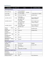
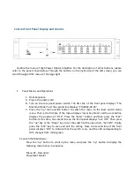
OPTON PTA5102Y-16 Manual Download Page 4


Description 

Unit 

Value 

Conditions / Notes 

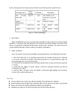
Mechanical Specifications


Dimension     
(LxWxH) 

mm 

483 

 422 

 88 

Carton:590 

 590 

 200 

Weight 

kg 

Net weight    11.5, 

gross weight :14.8 

Mounting 


19” EIA rack, 2U Rack 
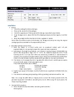


Installation 

1.


Unpack 


Check the package for obvious damage. 


Take out the device from the package. 


Check the appearance of the equipment for damage caused by transportation. 


If any damage occurs, please informed the shipping company and local agency in written 
form. 


Keep the package and the insertion for future upgrades or repairs. 

Note: When the device returns to the factory, any damage caused by not using the original 
packaging will be considered as the responsibility of user. 
 

2.


Assembly and Power Connections 

1.


Place  the  device  in  a  19-inch  wide  rack  or  equipment  cabinet  with  1.75-inch 
(approximately 4.5 cm) spacing between the upper and lower equipment. 

2.


According to the design requirements, our company’s maximum power 1550nmEDFA can 
work  in  the  temperature  range  of  0  °C  ~  50  °C.  An  ambient  temperature  of  25  °C  and 
humidity  which  is  no  more  than  95%  (non-condensing  conditions)  is  recommended.  If 
necessary, the equipment should maintain proper temperature and humidity within these 
limits. It is recommended that this equipment be operated in a low dust


environment. 

3.


The device can be powered by AC or regulated DC. When the AC and DC power supplies 
are used, the AC power is the main power source. 
The power requirements are as follows: 

AC input   


94-245 VAC, 50-60 Hz 

DC input   


36-60 VDC, floating 

Power consumption    

up to 50 W 

4.


The DC input power to the device must be the SELV source specified in CAN/CSA C22.2, No. 
950-95. 

5.


This device should have good grounding and the grounding resistance should be < 4Ω. 


Note:  Use  a  large  size  (#20  AWG,  or  larger)  wire  to  connect  the  chassis  ground  stud  to  the 
grounded  equipment  rack  before  connecting  the  circuit.  When  using  DC  input  power,  the 
chassis must be grounded. 


3.


  Optical Port Connection 

1.


Clean all optical connectors before connecting the transmitter. 
Cleaning steps: 

Summary of Contents for PTA5102Y-16

Page 1: ... also provide monitors and associated alarms for all vital characteristics The status and management of the device can be monitored and managed either from the LCD front panel display Web or remotely via Ethernet based SNMP The device also support multipul optical output by build in PLC splitter and FWDM 1310nm 1490nm optical multiplexer for Triple play FTTX network applications Feature Standard 1...

Page 2: ...www netlinkict com Diagram ...

Page 3: ...A Laser Bias current Pump 16 22dBm 3100mA 200mA 6dBm input Alarm range Out of 1800mA 4600mA Output Power Stability dB 0 1 6dBm Input Noise Figure dB 4 max 5 6dBm Input Isolation Input Output dB 30 Return Loss Input Output dB 55 Polarization Dependent Gain dB max 0 5 Polarization Mode Dispersion ps max 0 5 Electrical Specifications Communication Interface RJ45 RS 232 9600bps Input voltage VAC 1pc 2...

Page 4: ...y s maximum power 1550nmEDFA can work in the temperature range of 0 C 50 C An ambient temperature of 25 C and humidity which is no more than 95 non condensing conditions is recommended If necessary the equipment should maintain proper temperature and humidity within these limits It is recommended that this equipment be operated in a low dust environment 3 The device can be powered by AC or regulat...

Page 5: ...the transmitter s fiber optic connector can be cleaned with a 2 5mm cotton swab or the connector gasket can be removed to directly clean the fiber optic connector inside To remove the connector gasket unscrew the screws on the left and right sides of the gasket Do not screw the bolt with plastic sleeve on the gasket Slowly remove the connector pads from the rear panel of the transmitter and then r...

Page 6: ...o switch the menu to the laser switch status menu That is the first line of the menu displays Laser Key State and the second line displays the position of OFF Press the Enter button and then press the ESC button At this time the second line on the front panel displays Set OFF Then press the up key or the Down key to set the switch to the open state Set ON Finally press the ESC key to save and exit...

Page 7: ...State Laser Key State Menu 7 Pin Input Optical Power Menu 8 Pout Output Optical Power Menu 9 LD BIAS Pump1 Bias Current Menu 10 COOL CUR Pump1 Cooling Current Menu 11 LD TEMP Pump1 Temperature Menu 12 LD BIAS Pump2 Bias Current Menu 13 Power_1 5V Power Supply 1 Voltage Menu 14 Power_2 5V Power Supply 2 Voltage Menu 15 Temperature in Box Machine Temperature Menu 16 IP ADDR ...

Page 8: ...ntinue to operate when it issues a warning the warning can be eliminated by continuous self test of the equipment or restoration of the relevant system parameters to the normal range Some serious alarms can be eliminated by turning the power off and on again If the relevant parameters return to the normal range the alarm will automatically disappear Most of the warnings are triggered when the erro...

Page 9: ...prevent many potential problems by paying attention to the following information 1 Place the PUMP laser in an operating range where the ambient temperature is between 0 C and 50 C and other conditions meet the requirements It is recommended to place the Optical Amplifier in a low dust environment 2 Ensure that the rear panel fan and front panel socket holes are clear and the rear panel fan is runn...

Page 10: ... Connect the optical fibers of all ports before power on The optical connector cannot be plugged or unplugged while the machine is working The machine cannot move or shake while working ...

Reviews: