background image

HD3000

6-4

No

Step

Procedure

Photo

5

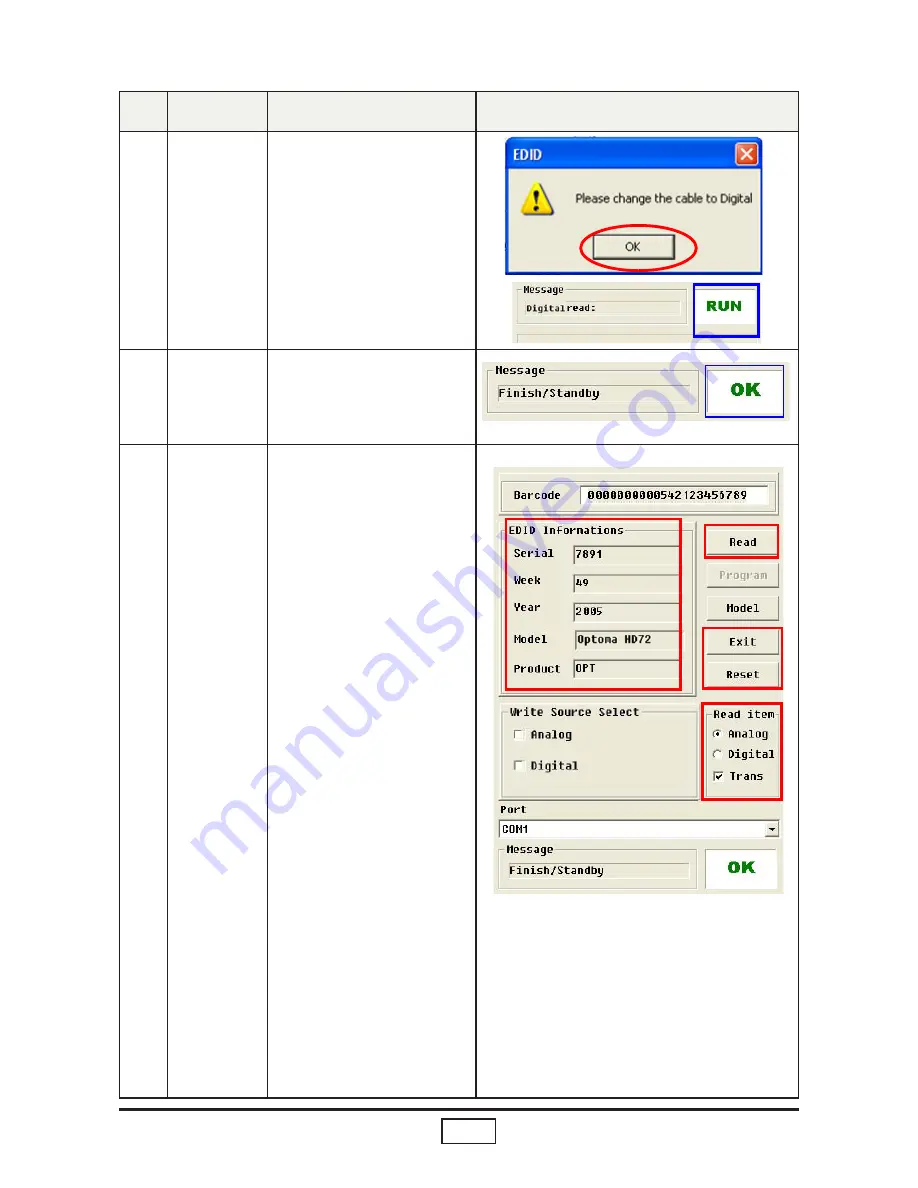
Change 

Cable to 

HDMI

- “Please Change the cable 
  to Digital” Message is 
  shown on the screen.

- Connect Port P3 of fixture 

  and HDMI port of HD3000 
  by DVI cable which link with 
  HDMI-DVI adapter.
- Click “OK”

6

HDMI 

finished

- When the EDID programn  
  is completed, the 
  message “OK” will appear 
  on the screen.

7

Check 

the whole 

process

. In the “Read Item” 
    Selections, choose the 
    Port that you use.
    Ex: If you use the Analog 
          (Digital) Port, choose 
          “Analog(Digital)” in the 
          “Read Item”.

(Note: After clicking “Read” , 
if the code in the Serial Blank 
is scrambled, please make a 
check in “Trans”.)

2. Click on “Read” to read 
    EDID information.
3. The “EDID Informations” 
    will show the result.
4. Click “Reset” to do the 
    next unit or “Exit” to close 
    the EDID program.

4

3

2.

Summary of Contents for ThemeScene HD3000

Page 1: ...______ Approved by ________________________________________ Model Name HD3000 Date Version Description 2006 05 29 V1 0 Initial Issue 2006 11 1 V2 0 amend content of Chapter 4 3 Inspection Procedure 2007 11 1 V3 0 Delete Lattice function upgrade procedure in Ch 5 Copyright Nov 2006 All Rights Reserved P N 36 R0102 001 Document R01 G04 01A SERVICE MANUAL ...

Page 2: ...iate the service that you offer them This manual is for technicians and people who have an electronic background Please send the product back to the distributor for repairing and do not attempt to do anything that is complex or is not mentioned in the troubleshooting Notice The information found in this manual is subject to change without prior notice Any subsequent changes made to the data herein...

Page 3: ...eer Wheel Front Cover Left and right Cover Front Panel and Stamping Foot 2 7 Chapter 3 Troubleshooting 3 1 Equipment Needed 3 1 Main procedure 3 1 Chapter 4 Function Test and Alignment Procedure 4 1 Test Equipment Needed 4 1 Inspection Item 4 1 Inspection Procedure 4 2 Chapter 5 Firmware Upgrade Procedure 5 1 Comparison Table 5 1 HDMIRX HDMITX 5 2 Gennum System Bias 5 5 OSD 5 7 MCU 5 9 Chapter 6 E...

Page 4: ...HD3000 III EDID Key In Procedure 6 2 Appendix Appendix A 7 1 Exploded Overview 7 1 Appendix B 7 4 I Serial Number System Definition 7 4 Reader s Response 7 5 ...

Page 5: ...8 60Hz 1280X768 72Hz 1366X768 50Hz 1366X768 60Hz 1920x1080p 48Hz 1920x1080p 50Hz 1920x1080p 60Hz 7 Connect I O port Input 3 HDMI input for HDMI signal switching 1 HDMI in from AV receiver 2 YPbPr through RCA connector 2 YPbPr RGBHV through BNC connector 1 VGA in through Dsub 15 connector 3 S video 3 composite 1 IR module with phone jack connector Output 1 HDMI output To AV receiver 1 HDMI output T...

Page 6: ...y Digital input 1 Video for HD3000 stand alone 640x480p 59 94 60Hz 720 1440 x480i 59 94 60Hz 720 1440 x576i 50Hz 720x480p 59 94 60Hz 720x576p 50Hz 1280x720p 50Hz 1280x720p 59 94 60Hz 1920x1080i 50Hz 1920x1080i 59 94 60Hz 1920x1080p 59 94 60Hz 2 Video for BigVizion 640x480p 59 94 60Hz 720 1440 x480i 59 94 60Hz 720 1440 x576i 50Hz 720x480p 59 94 60Hz 1280x720p 50Hz 1280x720p 59 94 60Hz 1920x1080i 50...

Page 7: ... Automatically recognizes the input signal and configures itself accordingly Automatically saves adjustments for future use 19 On Screen Menu Multi language English Spanish French 4 main items Image Display System Setup 1 2 Computer Compatible Analog input Compatibility Resolution V Sync Hz H Sync KHz VGA 640x480 60 31 5 640x480 72 37 9 640x480 75 37 5 US TEXT 720x400 70 31 5 SVGA 800x600 56 35 2 ...

Page 8: ...2 HD3000 2 1 Equipment Needed Chapter 2 Disassembly Process Item Photo Item Photo Screw Bit 107 Hex Sleeves 5mm Hex Sleeves 6mm Hex Socket Insert Bit ...

Page 9: ...NT 1 Board Power Board and Main Board No Procedure Photo 1 1 Press to open the front cover 2 Unscrew 8 HEX SOCKET CAP SCREWS to remove Top Cover 2 Unscrew 4 screws and 2 hex screws to remove CONNT 2 Board Press to open front cover CONNT 2 Board ...

Page 10: ...2 HD3000 No Procedure Photo 3 Unscrew 2 screws to remove CONNT 1 Board 4 Unscrew 4 screws and un plug 2 connectors to remove Power Board CONNT 1 Board Power Board ...

Page 11: ...2 HD3000 No Procedure Photo 4 Unscrew 3 screws red cir cle 6 copper pillars yellow circle and unplug 4 connec tors red square to remove Main Board and Back End Metal Main Board Back End Metal ...

Page 12: ...Photo 1 Unscrew 3 screws to re move AC Plug 2 Unscrew 2 screws and 2 hex screws to remove CONNT 3 Board and Back End Metal AC Plug CONNT 3 Board Back End Metal 2 3 Disassemble AC Plug CONNT 3 Board Keypad Board and IR Board ...

Page 13: ...2 HD3000 No Procedure Photo 3 Unscrew 6 screw nuts to remove Keypad Board 4 Unscrew 1 screw and tear the masking tape to remove IR Board 5 Remove mylar Keypad Board IR Board ...

Page 14: ...screw 1 screws to re move Gear Wheel 2 Unscrew 3 screws to re move front cover 3 Unscrew 2 screws to re move the Door Lock Gear Wheel Door Lock 2 4 Disassemble Geer Wheel Front Cover Left and right Cover front panel and Stamping Foot ...

Page 15: ...2 HD3000 No Procedure Photo 5 Unscrew 4 screws each to remove left and right Lateral Panel 6 Unscrew 10 screws to re move Front Panel Left and Right Lateral Front Panel ...

Page 16: ...2 HD3000 No Procedure Photo 7 Unscrew 4 screws to re move Stamping Foot Stamping Foot ...

Page 17: ... 1 Color Abnormal Ensure the Signal Cable and Source work Calibration Check Connect Board Check Main Board 2 No Image Image Abnormal Ensure the Signal Cable and Source work Check Main Board Check Connect Board 3 Sound Abnormal Ensure the Signal Cable and Source work Check Speaker Check Main Board Check Connect Board Chapter 3 Troubleshooting ...

Page 18: ... HDMI1 HDMI2 S Video 1 2 Video 1 2 3 YPbPr 1 2 3 VGA BNC 1 2 2 Sound Speaker 3 Remote Control 4 3 Inspection Procedure No Inspec tion item Inspection spec Equipment setting Test pattern 1 VGA port Image can not with flicker color abnormal shadow abnormal line and other abnormal condition If flicker and noise get in to OSD menu to adjust Frequency or Phase PC VGA HD3000 VGA IN Projector ...

Page 19: ...rojec tor screen bottom will get green It s normal and don t reject the HD3000 3 S Video 1 S Video 2 Image can not with flicker color abnormal shadow abnormal line and other abnormal condition DVD Player 480P HD3000 S Video In Projector DVD 4 Video 1 Video 2 Video 3 Image can not with flicker color abnormal shadow abnormal line and other abnormal condition DVD Player 480P HD3000 Video In Projector...

Page 20: ... other abnormal condition Chroma 2326 HD3000 BNC In Projector 7 Calibra tion 1 Get into ser vice mode Hot key to get into service mode press these button sequentially 2 Choose Video Calibration then press enter Chroma 2326 Signal 720P Pattern 94 White Note If the image color is abnormal please do calibration first 8 Speaker function If the sound is nor mal ...

Page 21: ...d hold 2 seconds more TX Code C01 H00 C01 H01 Update topro 5 6 on HDMITX RS232 MCU Code Update topro 1 2 on MCU RS232 1 Press left button and hold it 2 Then power on HD3000 and hold the left button more than 5 seconds Device 1 bin Device 4 bin Choose device by different area Updated OSD 1 2 on OSD RS232 X Device 5 bin Update gennum 1 2 on System BIAS RS232 X Fixture part number 42 86603G001 Compar...

Page 22: ...er Note There are two kinds of firmware program to update the jumper setting is different 1 FW file D02 H00 and D02 H01 for HDMIRX Jumper 3 4 on 2 FW file C01 H00 and C01 H01 for HDMITX Jumper 5 6 on 2 Software Set up Proce dure Step1 Excute updatetopro program Update program window will show up 1 HDMIRX HDMITX 3 4 on 5 6 on ...

Page 23: ...TX Selcect FW file TX code C01 H00 and C01 H01 4 Next Click download button to update new TOPRO file 5 Next Step1 Uplug power cord Step2 Press the switch on main board and hold it then plug in power cord The power light will turn to red Step3 Press power but ton to make power light turn to blue Wait for 2 seconds and release the switch on mainboard Updatetopro program will start to update software...

Page 24: ...HD3000 5 No Step Procedure Photo 6 Next When the software upgrade completely the OK message will show Note If next HD3000 needed to do the same upgrade procedure No1 3 pro cedure can be ingored ...

Page 25: ... 2 Select Port Com1 then connect PC and HD3000 by RS232 cable Program will connect automatically clicking Connect button is not needed 4 Next Click Device5 button to select file to update GENNUM Note Please make sure to select the correct file device5 bin 2 GENNUM System Bias Note Be careful When updating the software failure is not allowed It will cause all system failed and unrecoverable The onl...

Page 26: ...he file is correct 3 Click download button to start download procedure Note The update procedure is not allowed to be interrupted before click ing download button please make sure every procedure is ready and correct 8 Next After the program update completely OK message will show as the picture shows Note If next HD3000 needed to do the same upgrade procedure No1 3 pro cedure can be ingored After ...

Page 27: ...ase open top cover to set jump Note Set jumper 1 2 on 2 Software set up procedure Excute updateosd pro gram file 3 Update program will show as picture 4 Next 1 Select the Port Com1 then connect HD3000 and PC by RS232 cable 2 Click device1 to select files 3 Select the Flash memory needed to be updated ...

Page 28: ...it the power light turns to blue 7 Next Click download button to update OSD file 8 Next After the program update completely OK mes sage will show as picture shows Note If next HD3000 needed to do the same upgrade procedure No1 3 pro cedure can be ingored After fininshing update procedure please click Exit button to exit up dateosd program ...

Page 29: ... cover to set jump Note Set jumper 1 2 on 2 Software set up procedure Excute updateosd pro gram file 3 Next Update program will show as picture 4 Next 1 Select Port Com1 then connect HD3000 and PC by RS232 cable 2 Click device0 button to select file 3 Click Download but ton and wait for updating TOPRO file 1 2 3 ...

Page 30: ...ait for 5 seconds then release HD3000 left but ton Updatetopro pro gram will start to update software Progress bar shows the update progress 5 Next After the program update completely OK mes sage will show as the picture shows Note If next HD3000 needed to do the same upgrade procedure No1 3 pro cedure can be ingored After fininshing update procedure please click Exit button to exit up datetopro p...

Page 31: ...nformation maximum image size color characteristics factory pre set timings frequency range limits and character strings for the monitor name and serial number The information is stored in the display and is used to communicate with the system through a Display Data Channel DDC which sites between the display device and the PC graphics adapter The system uses this information for configuration pur...

Page 32: ...1 Port 3 Fixture P2 to HD3000 VGA Port by VGA Cable 2 Power On Fixture Power on Fixture 1 Execute EDID Program Click on EDID to execute EDID Program Item Photo Item Photo PC One additional monitor for checking the pro gram execution Setup Procedure EDID Key In Procedure No Step Procedure Photo P1 JP1 P3 P2 ...

Page 33: ... selection 2 Click on Model 3 Choose the EDID that responses to the model that you choose 3 Key in Serial Number 1 Key in the Serial Number into the Barcode blank space 2 Click Program 4 Change Cable to VGA Please change the Cable to VGA message is shown on the screen Connect the port P2 of fixture to the VGA port of HD3000 by VGA Cable Click OK 2 1 1 2 3 ...

Page 34: ...ompleted the message OK will appear on the screen 7 Check the whole process 1 In the Read Item Selections choose the Port that you use Ex If you use the Analog Digital Port choose Analog Digital in the Read Item Note After clicking Read if the code in the Serial Blank is scrambled please make a check in Trans 2 Click on Read to read EDID information 3 The EDID Informations will show the result 4 C...

Page 35: ...7 HD3000 Appendix A Exploded Overview 1 HD3000 Unit ...

Page 36: ...80 R0103G001 PCBA CONNECTOR 2 BOARD VX3000 12 61 R0109G001 HEX SPACER M3 W5mm L20mm COPPER VX3000 13 80 R0101G001 PCBA MAIN BOARD VX3000 14 75 R0101G001 BUY ASSY POWER SUPPLY MODULE PT4503 15 42 R0104G001 WIRE AC PLUG TO POWER 3P 50mm VX3000 16 61 R0106G001 LATERAL PANEL ALUMINUM ANODIZ VX3000 17 42 R0103G001 WIRE POWER TO M B 8P 90mm VX3000 18 75 R0102G001 STAMPING FOOT MODULE VX3000 PINGOOD 19 8...

Page 37: ...01G001 TOP COVER ALUMINUM ANODIZED VX3000 32 51 R0102G001 DOOR LOCK RIB BLACK DL 003 33 85 4A323 040 SCREW FLATE MECH M3 4 BLACK 34 85 005AGG065 SCREW HEX I O 4 40 H5 L6 5 NI NYLOK GREEN 35 61 R0112G001 CONDUCT IO OF FROM END METAL VX3000 36 61 R0111G001 CONDUCT IO OF BACK END METAL VX3000 37 41 R0102G001 EMI TBP H013N 235mmx10mm VX3000 38 41 R0101G001 EMI TBP H013N 400mmx10mm VX3000 39 51 R0106G0...

Page 38: ... 3 EX OR01603AAAAPA1001 This label OR01603AAAAPA1001 represents the whole serial number for HD3000 P It s produced on 03s week of 2006 for universal area and its serial code is 1001 O Optoma B Z OEM Product code ex R01 HD3000 Y Last number of the year ex 2006 6 Week of year Model Code ex AAAAPA HD3000 P Serial code from 0001 3 6 1 2 5 4 ...

Page 39: ...ut this service manual Reader s basic data After your finishing this form please send it back to Coretronic Customer Service Dept by fax 886 3 563 5333 A What do you think about the content after reading HD3000 Service Manual Unit Excellent Good Fair Bad 1 Introduction 2 Disasaembly Procedure 3 Troubleshooting 4 Function Test Alignment Procedure 5 Firmware Upgrade Procedure 6 DDC key in Procedure ...

Reviews: