Optocore DD8RP Operating Manual Download Page 2


DD8RP


2 / 15 

rev. 1.0


Important Safety Instructions 


Please read this manual carefully. 


Please keep this operating manual in a safe place. 


Heed all warnings. 


Follow all instructions. 


This device may only be used in accordance to the information provided in this operating 
manual. Ensure that all recommendations, especially the safety recommendations as detailed 
in this operating manual, are followed before and during the usage of the device. 


Do not use this device near water, for example, in moist or damp rooms. 


Clean only with a dry cloth. 


Do not block or cover any ventilation slits. Install the device in accordance to the operating 
manual. 


Do not install or place the device near any heat source such as radiators, power-amplifiers, 
stoves, or any other heat producing equipment. 


Protect the power cord from being walked on, crushed, pinched, or damaged in any other way. 
Pay special attention to plugs and sockets of the device. 


Never switch on power amplifiers before the complete system is stable and the level meters of 
the OPTOCORE CONTROL software indicate a normal level. 


Do not place this device on an unstable table, tripod, cart, etc. The device may fall, causing 
serious damage to the device, and a risk of injury. 


The device can only be removed from the power supply by pulling the plug. This must be 
freely accessible at all times. The device has to be disconnected during lightning storms or 
when unused for long periods of time. 


The device must be grounded; any disconnection of the grounding is not permitted. 


The switched-mode power supplies operate with high voltage. Coming into contact with them 
can lead to considerable electric shocks, which may result in death. 


Only use attachments specified by the manufacturer. 


This device contains no user serviceable parts: only refer to authorized, qualified service 
personnel for any servicing. 


Your warranty will be voided if you tamper with the internal components. 

Summary of Contents for DD8RP

Page 1: ...DD8RP Operating Manual Rev 1 0 Operating Manual for OPTOCORE DD8RP REPEATER MEDIA CONVERTER MODULE Copyright 2007 All rights reserved OPTOCORE GmbH Lisbergstr 7 81249 Munich Germany ...

Page 2: ...other way Pay special attention to plugs and sockets of the device Never switch on power amplifiers before the complete system is stable and the level meters of the OPTOCORE CONTROL software indicate a normal level Do not place this device on an unstable table tripod cart etc The device may fall causing serious damage to the device and a risk of injury The device can only be removed from the power...

Page 3: ...rtainment lighting control apparatus for professional use E1 Residental E2 Commercial and light industrial E3 Urban outdoors E4 Controlled EMC environment e g broadcast and TV studio E5 Heavy industry The product is intended for the use in moderate climate Ventilation Do not block or cover any ventilation slits Install the device in accordance to the operating manual Leave sufficient ventilation s...

Page 4: ...afety This product is a Laser Class 1 product It complies with IEC 60825 1 FDA 21 CFR 1040 10 and 1040 11 Interference of external objects and or liquids with the device Never push objects of any kind into the device through openings in the casing They may come in touch with dangerous voltage points or short out parts that could result in a fire or electric shocks Never spill liquid of any kind on...

Page 5: ...apparatus for professional use EN 55103 1 Emission EN 55103 2 Immunity The authorised declaration and compatibility certification lies with the manufacturer and can be viewed on request Responsible as manufacturer is OPTOCORE GmbH Lisbergstr 7 81249 Munich Germany Represented by Marc Brunke Managing Director N B The awarding of the CE label confirms the compliance with legal directives issued for ...

Page 6: ... 3 CE Conformity 5 Eye Safety 5 Device Description 7 Front Panel 8 Rear Panel 8 Device Details 9 LINK Ports 9 Power Supply 9 Connectors and Cables 9 Starting Up 10 Hardware Connection 10 Connection Tables 11 Technical Specifications 12 Dimensions and Weight 13 Warranty and Liability 14 Shipping Contents 14 Company Information 15 ...

Page 7: ... depends on the implemented optical transceiver This allows the configuration exactly appropriate for the application E g one LINK may extend the distance between two Optocore devices in an OPTOCORE OPTICAL DIGITAL NETWORK while the other LINKs are used in totally different networks with non Optocore protocols LEDs on the front give detailed information about the status and operating state of each...

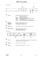
Page 8: ...operation OVP LED Indicates over voltage protection 300 VAC PWR 1 LED AC Power supply 1 is working correctly PWR 2 LED DC Power supply 2 is working correctly RS232 plug D Sub 9 RS232 connection for remote control and update via PC USB plug and LED USB connection for remote control via PC LED ON indicates USB is connected LED blinking indicates data traffic Rear Panel LINK 1 4 Independent LC type o...

Page 9: ... or transformers The power supply unit is 400 VAC tolerant and protected against high current The OVP Over Voltage Protection LED on the front will indicate over voltage at 300 V simultaneously suppressing the normal function of the device When the OVP LED is lit immediately disconnect the device from the power line to prevent any damage to the device The power input has a fuse replaceable without...

Page 10: ...on Port A of the LINK 1 is used as interface to the DD32E with ID 2 port B as interface to the DD32E with ID 2 Fig 1 DD8RP between two DD32E functioning as repeater in order to extend the distance of the multimode connection The second example in Fig 2 shows an application where the two DD8RP work as repeater and media converter The first DD8RP functions as a converter from multimode to monomode t...

Page 11: ...male XLR Pin out RS232 Port RS232 Power Channel RXD TXD Internally Bridged 5VS GND Pin 3 2 1 4 6 7 8 9 5 Use 1 modem cable male female to connect to PC D Sub 9 female 5 1 9 6 Locking system acc to 4 40 UNC Pin out USB Port USB Channel VBUS D D GND Pin 1 2 3 4 USB device connector ...

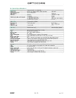
Page 12: ...00 VAC tolerant Frequency 50 60 Hz Power consumption 4 14 VA dependent of number of SFPs installed Fuse D1 0 A slow behavior glass 5 mm x 20 mm acc to UL 48 14 Inrush current limit 7 A Protection circuit 400 VAC tolerance over voltage over current and over temperature monitor Security classification Class 1 basic insulation connected to the protective grounding conductor Security regulations Harmo...

Page 13: ...83 19 438 17 25 44 1 73 136 5 35 44 1 73 1RU Front plate Front elements Handles Add 6 0 24 Rear elements Add 15 0 6 Weight 2 0 kg 4 4 lbs Modifications that serve the purpose of technical improvement of the device may be carried out without prior notification ...

Page 14: ...e contact your distributor dealer Our web site http www optocore com provides a complete list of Optocore distributors dealers Always ensure the careful handling of the device If possible transport or shipping should always occur in special shock absorbing transport cases If these are not available we recommend well upholstered packaging such as the coated carton in which the device was delivered ...

Page 15: ...DD8RP 15 15 rev 1 0 Company Information Mailing Address OPTOCORE GmbH Lisbergstr 7 D 81249 Munich Germany Telephone 49 0 89 8999640 Facsimile 49 0 89 89996455 Internet www optocore com Email ...

Reviews: