TROUBLESHOOTING
SNAP-LCSX AND LCSX-PLUS Installation Guide
24
Power Supply Recommendations
Opto 22 recommends that the SNAP-LCSX or LCSX-PLUS be powered with an Opto 22 SNAP-PS5 power
supply. The SNAP-PS5 can provide sufficient power for the controller, a B3000 brain board, 32 digital I/O
points, and up to eight analog I/O points.
In lieu of the SNAP-PS5, Opto 22 recommends a 5-volt linear supply with adequate current ratings for the load.
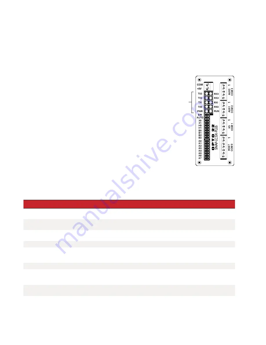
LED Descriptions
The SNAP-LCSX and LCSX-PLUS include the following LEDs:
PWR
— If the PWR LED is on, power is applied to the controller.
RUN
— If the RUN LED is on, the controller is working properly. If the
RUN LED blinks (or is off when the PWR LED is on), contact Opto 22
Product Support.
TX
— Each communication port has a TX LED, which is on whenever
the controller is actively transmitting data through that port.
RX
— Each communication port also has an RX LED. It is on
whenever the controller is actively receiving data through that port.
TROUBLESHOOTING
If you encounter a problem while installing or using the SNAP-LCSX or LCSX-PLUS controller, check this section
for suggestions.
if you need to contact Opto 22 Product Support.
LEDs
If you see this
It means
Try this
RUN LED stays off.
Power is incorrectly applied to the con-
troller.
Check power supply connections.
PWR LED stays off.
Power is incorrectly applied to the con-
troller.
Check for voltage. Check wiring polarity.
RUN LED is off but PWR LED
is on.
The controller has an internal problem.
Call Opto 22 Product Support.
RUN LED blinks.
Voltage is outside specifications.
Check power supply voltage at the controller input terminals.
RUN LED blinks.
There is a kernel or boot error. Kernel
(firmware) may be corrupted.
Remove jumper X1 and cycle power to the controller. If the
RUN LED is solid, download new firmware. If the RUN LED
still blinks, call Opto 22 Product Support.
RX LED is stuck on.
Wiring polarity problem.
Try swapping the TX+ and TX- wires.
Controller cannot transmit to
PC.
Configuration jumpers were changed
without cycling power.
•
Cycle power and retry transmission.
•
If using RS-232 port on SNAP-LCSX, make sure pin 4
(RTS) and pin 5 (CTS) are jumpered.
No communication to host PC
and no TX/RX LEDs.
Communication problems.
Check the PC serial port.
No communication to host PC.
RX LED is on, but TX LED is
off.
Communication problems.
Check controller address, baud rate, and ASCII/binary set-
tings.
See “Setting the Faceplate Jumpers” on page 7
.


