


- 31 -
Features and Technical Specifications: Outdoor Access Point/Client Bridge
and IP Video Server
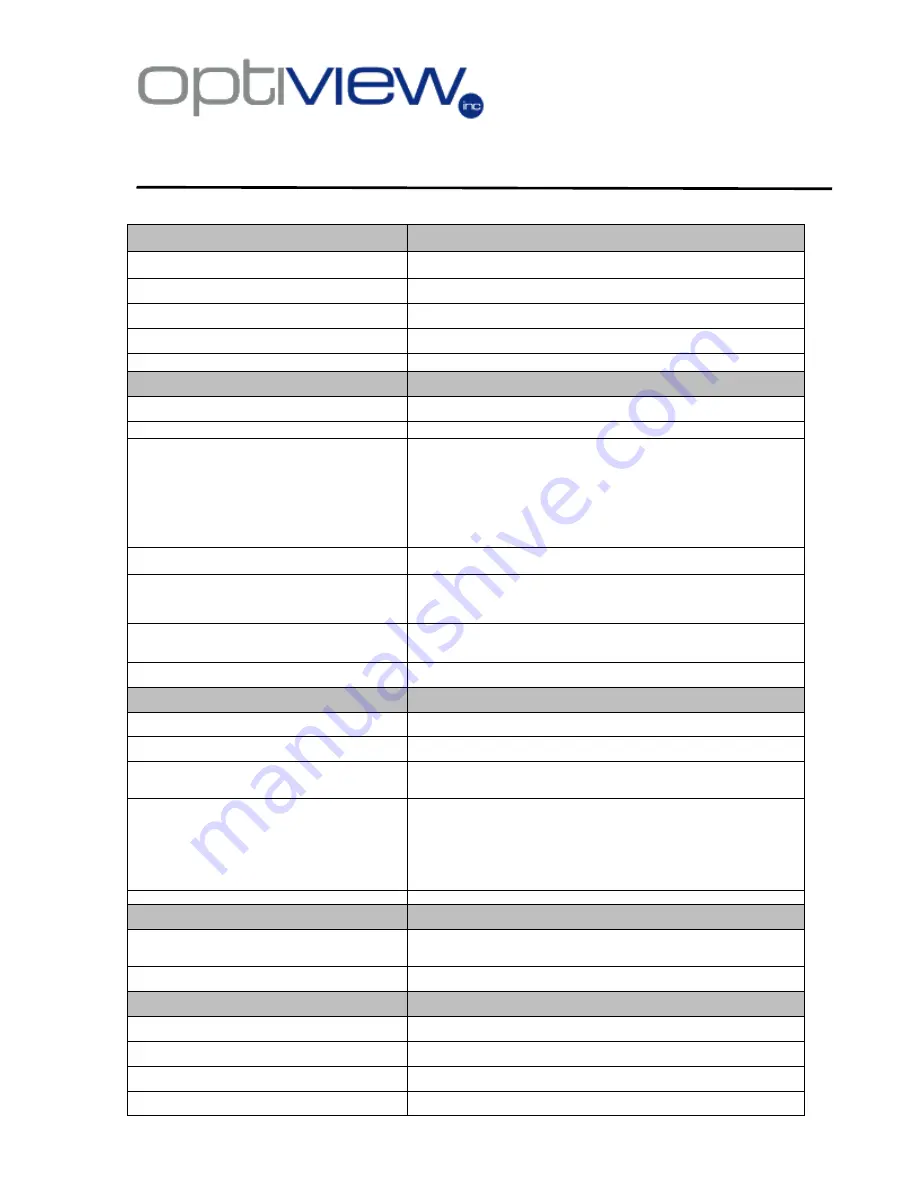
Technical Specifications: Outdoor Access Point/Client Bridge
Technical Specifications
Details
Data Rates
1, 2, 5.5, 6, 9, 11, 12, 18, 24, 36, 48, 54 Mbps
Standards
IEEE802.11b/g, IEEE802.1x, IEEE802.3, IEEE802.3u
Compatibility
IEEE 802.11g/ IEEE 802.11b
Power Requirements
Active Ethernet (802.3af)
– 48 VDC/0.35Amps.
Regulation Certifications
FCC Part 15, ETSI 300/328/CE
RF Information
Frequency Band
2.400•2.4835 GHz (US, EU)
Media Access Protocol
Carrier Sense Multiple Access with Collision Avoidance (CSMA/CA)
Modulation Technology
Orthogonal Frequency Division
Multiplexing (OFDM)
DBPSK @ 1Mbps
DQPSK @2Mbps
CCK @ 5.5 & 11Mbps
BPSK @ 6 and 9 Mbps
QPSK @ 12 and 18 Mbps
16-QAM @ 24 and 36 Mbps
64-QAM @ 48 and 54 Mbps
Receive Sensitivity (Typical)
88dBm @ 6Mbps
70dBm @ 54Mbps
Available transmit power
Up to 26dBm @ 1~24Mbps
23dBm @ 36Mbps
21dBm @ 48Mbps
20dBm @ 54Mbps
Antenna
Option A: 9dBi Internal(Patch)
Option B: 5dBi External (Dipole)
Option C: 16dBi Built-in (Patch)
RF Connector
SMA (Fr) Type (Optional for External Antenna use)
Networking
Topology
Ad-Hoc, Infrastructure
Operation Mode
Point-to-Point/ Point-to-Multipoint Bridge/Client Router/ AP/ WDS/ Repeater
Interface
.
Wireless IEEE802.11b/g
.
One 10/100 RJ-45 port
.
RS232 connector
Security
.
IEEE802.1x Authenticator / RADIUS Client (EAP-MD5/TLS/TTLS) Support in
AP Mode
.
WPA /WPA2
.
MAC address filtering
.
Hide SSID in beacons
.
User isolation
.
NAT in CR mode
IP Auto-configuration
DHCP client/server
Management
Configuration Interface
.
Web-based configuration (HTTP)
.
SNMP V1, V2c
.
Telnet
Firmware Upgrade
Upgrade firmware via web-browser
Physical
Dimensions
163.8(L)mm * 135.2(W)mm * 47.0(H)mm
Weight
1.2 Kg (2.6 lbs)
Temperature Range
Operating: 0°C to 60°C (32°F to 140°F) -
Storage: -20°Cto 80°C (-4°F to 176°F)
Humidity (non-condensing)
5%~95% Typical