7
5. Accessories
A.
5X lenses
B. Power adapter
6. Cleaning and maintenance
Keep the lens inspection station dry and clean. Please clean it with lens cleaner or soft cloth.
Caution: please do not clean with alcohol or any corrosive cleanser to avoid damage of the surface.
7. Trouble Shooting Guide
1) Connect the power and turn on the machine. If the light is not on, it may be caused by the bad connection of
the power socket. Rotate the power adapter connection port slightly to check if the machine could light up.
2)When the machine uses the battery power, if the light of the lower inspection window flashes, it means the
voltage is lower than 2.8V, please charge the batteries or use AC power.
If it still can’t work, please contact the Repair department or an authorized distributor.
8. Specifications:
1)
Power: AC 100-240V 50-60Hz 0.4A
2) Power Adapter: DC 5V-6.5V 3A (6.5V MAX)
3) Dimension: 230*150*320mm
4) Weight: 1.65kg
5) Optional accessory
:
18650 rechargeable battery(12580mWh) * 2
Subject to change in design or specifications without advance notice
Version 1.0
- 8 -
6
If Lens stress has not been dealt with properly, the patient looks forward without any problem, but when he looks
aside, he would feel uncomfortable and unclear view exists. This situation usually appears on the full or half frame
eyeglasses, but not for the rimless ones.
The stress of PC le
ns can’t be avoided. However, the imaging quality will be much better if the lens stress is
small.
5) Function III - Final Inspection
Steps:
A
. Put PAL/Inspection TOP lens on the upper window. The direction mark is aligned with U-shaped groove.
B. Put Inspection BOTTOM lens on the lower window. The direction mark is aligned with U-shaped groove.
C. Put the lens between the inspection lenses. Observe the surface of the lens.
D. Scratching, bubbling and other coating problems can be checked out.
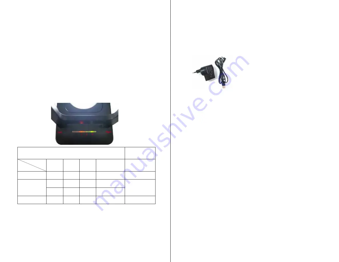
4. Operation Indicator Light
Operation Indicator Light Instructions
The order of the
indicator lights
Indictor
Status
Operation
Indicator 1
Operation
Indicator 2
Operation
Indicator 3
Note
At the battery chamber
side, from left to right
:
5V DC power, without
battery
flash
on
on
Without battery,
indicator 1 flashes
Operation Indicator 1
:
Charging(red)
5V DC Power, with
battery
on
off
on
The batteries are not
fully charged
Operation Indicator 2
:
Full(green)
off
on
on
The batteries are fully
charged
Battery Power
off
off
on
5V DC power is not
connected
Operation Indicator 3
:
Booster(green)
- 7 -


