background image

0

50V

70V

100V

4

Ω

8

Ω

16

Ω

SPEAKERS
LINE
OUTPUT

POWER
STAGE

PRIORITY

CONTROL

INPUT

MASTER
PRIORITY

MASTER

PROGRAM

PRI-PRO

LINK

PROGRAM

PRIORITY

PROTECTION

PRIORITY OUTPUT

PRIORITY INPUT

PROGRAM OUTPUT

PROGRAM INPUT

SURETY
PAGING

FAIL

SURVEILLANCE

Priority & Control Signal

Audio

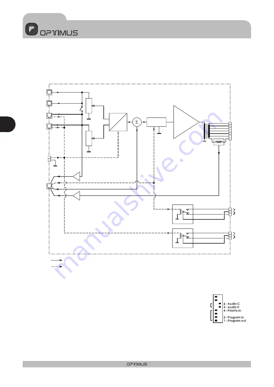
5. DIAGRAMA DE BLOQUES

6. CONFIGURACIÓN DE FÁBRICA

Por defecto, la configuración de fábrica de las etapas de potencia es la
siguiente:

Contacto de prioridad del RJ45 del conector PRIORITY OUTPUT: ON

Contacto de prioridad del RJ45 del conector PRIORITY INPUT: ON

Unión de la señal de los canales PRIORITY y PROGRAM: OFF

Unión de la pantalla del cable y el conector hacia la massa del
amplificador: ON

ON

OFF

PRI-PRO LINK

PRI-PRO LINK

SHIELD-GND

LINK

SHIELD-GND

LINK

7 - Priority ctrl. in

7 - Priority ctrl. in

8 - Priority ctrl. out

8 - Priority ctrl. out

3 - Priority out

3 - Priority out

DIPSWITCH CONFIGURATION

Otras configuraciones

JP1 (puente interno) = OFF

JP2 (puente interno) = ON
Surveillance Shield - Ground Link

E S PA Ñ O L

AMPLIFICADORES UP-366, UP-246, UP-126 y UP-66

Esp

1 0

UP-366, UP-246, UP-126 y UP-66

Versión 1.1

Summary of Contents for UP-126

Page 1: ...UP 66 UP 126 UP 246 UP 366 Nº Manual de instrucciones AMPLIFICADOR Operating instructions AMPLIFIER Español Español English English ...

Page 2: ......

Page 3: ...OSTERIOR 5 4 EL SISTEMA DE VENTILACIÓN 9 5 DIAGRAMA DE BLOQUES 10 6 CONFIGURACIÓN DE FÁBRICA 10 7 CARACTERÍSTICAS TÉCNICAS 11 8 CERTIFICADO DE GARANTÍA 12 Esp ESPAÑOL AMPLIFICADORES UP 366 UP 246 UP 126 y UP 66 3 UP 366 UP 246 UP 126 y UP 66 Versión 1 1 ...

Page 4: ... se selecciona el canal de Priority es decir cuando se une el pin nº 6 con el pin nº 8 en el conector RJ45 de la Entrada de Prioridad Se ilumina cuando actúa la Protección pudiendo ser debido a una sobrecarga o cortocircuito en la línea de altavoces o bien por un exceso de la temperatura interior Se ilumina cuando el a m p l i f i c a d o r e s t á funcionando tanto en alimentación de Red como de ...

Page 5: ...mador de alimentación asegura el uso de diferentes tensiones de red Estos amplificadores salen de fábrica preparados para funcionar a 230 V c a Bajo pedido se pueden suministrar preparados para otros voltajes Se encuentra situado en el cajetín inferior de la base de alimentación También hay un recambio en el mismo cajetín Esta alimentación permite el uso de estos aparatos en instalaciones de segur...

Page 6: ...ida 60W Potencia absorbida por cada transformador de 10W 10W B Potencia total absorbida 60W Potencia absorbida por cada transformador de 10W 5W C Potencia total absorbida 60W Potencia absorbida por cada transformador de 10W 2 5W A Potencia total absorbida 240W Potencia absorbida por cada transformador de 40W 40W B Potencia total absorbida 240W Potencia absorbida por cada transformador de 40W 20W C...

Page 7: ...ITY INPUT PRIORITY OUTPUT PROGRAM INPUT PROGRAM OUTPUT ON OFF POWER AMPLIFIER 240W RMS 312W IHF UP 246 Engineered in EU Spain Made in China OPTIMUS S A PRI PRO RJ CONNECTION 6 PRIORITY 8 METAL SHIELD GND WHEN BALANCED 7 8 6 5 3 2 1 DIPSWITCH CONFIGURATION ON OFF PRI PRO LINK SHIELD GND LINK 7 Priority ctrl in 6 Audio C 5 Audio H 4 Priority in 8 Priority ctrl out 3 Priority out 2 Program in 1 Progr...

Page 8: ...ermiten separar la pantalla del cable de la masa interna del aparato para cada uno de los conectores RJ 45 Normalmente están en posición ON pantalla y masa del aparato unidas Para separarlas debe situarse el dipswitch correspondiente en OFF Estos contactos permiten la activación de la prioridad facilitando el c a b l e a d o d e l a instalación El diagrama de bloques de la figura 8 muestra un ejem...

Page 9: ...el aparato superase los 110ºC se activaría la protección del aparato Para sustituir los ventiladores en caso de avería siga las figuras 10 y 11 4 EL SISTEMA DE VENTILACIÓN 14 Pin number 1 OSCILLATION INPUT OSCILLATION OUTPUT 1 PROTECTION OUTPUT OSCILLATION OUTPUT 2 Pin number 6 PRIORITY OUTPUT Pin number 7 24VDC OUTPUT 8 Shield Pin number 3 Pin number 4 Pin number 5 Pin number GND 1 8 1 8 JP2 puen...

Page 10: ...l RJ45 del conector PRIORITY OUTPUT ON Contacto de prioridad del RJ45 del conector PRIORITY INPUT ON Unión de la señal de los canales PRIORITY y PROGRAM OFF Unión de la pantalla del cable y el conector hacia la massa del amplificador ON ON OFF PRI PRO LINK PRI PRO LINK SHIELD GND LINK SHIELD GND LINK 7 Priority ctrl in 7 Priority ctrl in 8 Priority ctrl out 8 Priority ctrl out 3 Priority out 3 Pri...

Page 11: ... 65 1 kHz 50 18 000 Hz 3 dB 1 programa 0 dBu 1 prioridad 0 dBu 775 mV programa y prioridad 100 V 70 V 50 V 4 8 16 ohms Volumen de programa y de prioridad 230 V c a 7 5 VA 16 VA 9 2 VA 16 VA 253 VA 138 VA 460 VA 736 VA 482 6 w x 88 8 h x 368 5 d Placa frontal en hierro pintada azul Tapa en hierro pintada negra 80 dB 24 V c c 110º C 95º C Ventilador frontal 100º C Ventilador frontal 65º C Ventilador...

Page 12: ...nimiento 5 La garantía carecerá de validez cuando se observe Enmiendas o tachaduras en los datos del certificado de garantía o factura de compra Falta de factura original o falta de fecha en la misma Falta de número de serie o lote en el equipo 6 En el caso de ordenadores P C la garantía no cubrirá la eliminación de virus informáticos restauración de programas por este motivo o la reinstalación de...

Page 13: ... FRONT VIEW 14 3 REAR VIEW 15 4 VENTILANTION SYSTEM 19 5 BLOCK DIAGRAM 20 6 FACTORY SETUP 20 7 TECHNICAL SPECIFICATIONS 21 8 GUARANTEE 22 13 UP 366 UP 246 UP 126 and UP 66 Version 1 1 Eng ENGLISH AMPLIFIERS UP 366 UP 246 UP 126 and UP 66 ...

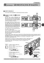
Page 14: ...ights up when the priority channel is selected i e when pin no 6 is linked to pin no 8 at the priority input RJ45 connector This lights up when the protection circuit has been activated either as a result of an overload or short circuit in the speaker line or overheating inside the unit This lights up when the amplifier is connected to the mains supply or is being powered by a battery source This ...

Page 15: ...mounted If the signals are also connected through the signal circuits it is advisable to remove the jumpers between the signal mass and the frame of all the units but one It is activated when the protection of the amplifier fails or when the power suplí of the amplifier is off Attention Keep the unit away from water or splatterings of any type PRIORITY CTRL INPUT GND PRIORITY INPUT PRIORITY OUTPUT...

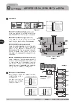
Page 16: ...B 50V 50V 50V 50V 70V 70V 70V 70V A A A A 100V 100V 100V 100V A Total input power 60W Power absorbed by each 10W transformer 10W B Total input power 60W Power absorbed by each 10W transformer 5W C Total input power 60W Power absorbed by each 10W transformer 2 5W A Total input power 120W Power absorbed by each 20W transformer 20W B Total input power 120W Power absorbed by each 20W transformer 10W C...

Page 17: ...OWER AMPLIFIER 240W RMS 312W IHF UP 246 Engineered in EU Spain Made in China OPTIMUS S A PRI PRO RJ CONNECTION 6 PRIORITY 8 METAL SHIELD GND WHEN BALANCED 7 8 6 5 3 2 1 DIPSWITCH CONFIGURATION ON OFF PRI PRO LINK SHIELD GND LINK 7 Priority ctrl in 6 Audio C 5 Audio H 4 Priority in 8 Priority ctrl out 3 Priority out 2 Program in 1 Program out SURVEILLANCE SURVEILLANCE RJ CONNECTION 1 OSC IN 2 NC 3 ...

Page 18: ...the cable shield from the internal mass of the unit for each of the RJ 45 connectors They are normally in the ON position shield and device mass connected To separate them place the corresponding dipswitch in the OFF position Priority is activated by means of these contacts facilitating the wiring of the installation The block diagram see figure 8 shows a typical installation example 12 13 OUTPUT ...

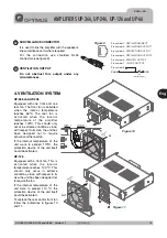
Page 19: ...it itself would be activated To replace the rear and or front fan follow the indications in figures 10 and 11 4 VENTILATION SYSTEM 14 GND 1 8 1 8 JP2 internal jumper 15 ON OFF SUR VEI LLA NC E RJ4 5 CO NN ECT ION 7 8 6 5 2 3 1 1 OSC IN 2 NC 3 OSC OU T 1 4 PRO TEC T 5 OSC OU T 2 6 PRI OU T 7 24 VDC OU TPU T 8 MET AL SHIE LD GN D DIP SW ITC H CO NFI GU RAT ION ON OFF 8 Prio rity ctrl out 7 Prio rity...

Page 20: ... Output connector ON Priority contact from the RJ45 Priority Input connector ON Priority and Program Audio link OFF Cable and RJ45 shield link to amplifier ground ON ON OFF PRI PRO LINK PRI PRO LINK SHIELD GND LINK SHIELD GND LINK 7 Priority ctrl in 7 Priority ctrl in 8 Priority ctrl out 8 Priority ctrl out 3 Priority out 3 Priority out DIPSWITCH CONFIGURATION OTHER CONFIGURATION JP1 internal jump...

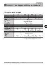
Page 21: ... dB 1 program 0 dBu 1 priority 0 dBu 775 mV program and priority 100 V 70 V 50 V 4 8 16 ohms Program and priority volume 230 V c a 7 5 VA 16 VA 9 2 VA 16 VA 253 VA 138 VA 460 VA 736 VA 482 6 w x 88 8 h x 368 5 d Iron front panel blue painted Iron cover black painted 80 dB 24 V c c 110º C 95º C Front fan 100º C Front fan 65º C Rear fan 100º C Front fan 65º C Rear fan 100º C 2 10 kg 8 6 kg 13 6 kg 1...

Page 22: ...the following is observed Amendments or corrections made to the details of the guarantee certificate or purchase invoice Failure to produce the original invoice or the absence of a date on this Absence of the serial or batch number on the equipment 6 In the case of personal computers the guarantee will not cover the elimination of computer viruses the restoration of programmes damaged by these or ...

Page 23: ......

Page 24: ...3 300 Fax 34 972 218 413 E mail export optimus es E 48006 BILBO Zumalakárregui 48 Tel 944 598 116 122 775 Fax 944 730 596 E mail bilbo optimus es Tel 944 E 46015 VALENCIA Av Maestro Rodrigo 101 Tel 963 461 039 Fax 963 461 038 E mail valencia optimus es E 41007 SEVILLA Ruiz de Alarcón 25 Tel 954 578 280 Fax 954 572 188 E mail sevilla optimus es E 15006 A CORUÑA Novoa Santos 27 Tel 981 298 400 Fax 9...

Reviews: