Optimum OPTi drill RD 3 Operating Manual Download Page 36

OPTIMUM

M A S C H I N E N   -   G E R M A N Y

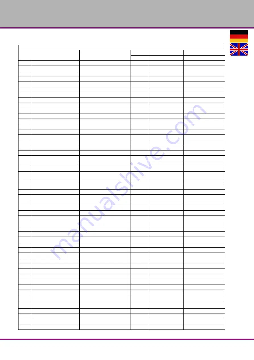
Ersatzteile - Spare parts

Version 1.0.2   2017-04-11

 36

Originalbetriebsanleitung

RD3

DE

Ersatzteilliste - Spare part list

Pos.

Bezeichnung

Designation

Menge

Grösse

Artikelnummer

Qty.

Size

Item no.

1

Schwenkfuß

Swivel Base

1

033350351

2

Säulenfuß

Column Base

1

033350352

3

Zahnstange

Rack

1

033350353

6

Federscheibe

Spring Washer

6

M12

7

Sechskant schraube

Hex. Head Screw

6

M12x50

8

Radial Arm

Radial Arm

1

033350358

9

Zahnstange Ausleger

Movable Rack

1

033350359

10

Sechskant schraube

Hex. Socket Head Screw

4

M6x15

11

Skala

Scale

1

0333503511

12

Niet

Rivet

2

Ø2

13

Unterlegscheibe

Washer

2

Ø10.5xØ27x3t

0333503513

14

Buchse Klemmgriff

Lock Handle Bushing

2

0333503514

15

Klemmgriff

Lock Handle

2

0333503515

16

Stahlband

Band Steel

1

0333503516

17

Senkkopfschraube

Flat Round Head Screw

2

M5x8

18

Griff für den Ausleger

Knob  Set

1

0333503518

19

Flanschring Säule

Column Flange Ring

1

0333503519

20

Kopfplatte Säule

Column Head Set

1

032352020

22

Schlauchtülle

Hose Bushing

1

0333503522

23

Schneckenwelle

Worm Shaft

1

0333503523

24

Buchse

Bushing

1

0333503524

25

Halterungsbaugruppe Höhenver-

stellung

Head Raise Bracket Assembly

1

0333503525

26

Sechskant schraube

Hex. Socket Head Screw

4

M6x25

27

Kurbel Auf / Ab

Up-Down crank

1

0333503527

29

Knopf

Knob

1

0333503529

30

Bohrkopfgehäuse

Head Body

1

0333503530

31

Pinolenkegel

Spindle Taper Sleeve

1

0333503531

32

Sicherungsring

C-Retaining ring

1

Ø3xØ80

0333503532

33

Äußere Lagerplatte

Outer Bearing Plate

1

Ø105xØ66x2.5t

0333503533

34

Senkkopfschraube

Cross Round Head Screw

3

M6x10L

35

Kappe

Cap

1

032353535

36

Sechskant schraube

Hex. Socket Head Screw

4

M6x20L

37

Keilriemenscheibe Spindel

Spindle Pulley

1

0333503537

38

Sicherungsmutter Spindel

Spindle Locknut

1

0333503538

39

Abdeckung Hauptwelle

Main Shaft Cover

1

0333503539

40

Senkkopfschraube

Cross Round Head Screw

4

M5x10L

41

Anzugsstange

Draw bar

1

MT12xP1.75

0333503541

42

Abdeckung Hauptwelle

Main Shaft Cover

1

0333503542

43

Keilriemenabdeckung

Belt Cover

1

0333503543

44

Seitenplatte (links)

Side Plate (left)

1

0333503544

45

Seitenplatte (rechts)

Side Plate (Right)

1

0333503545

46

Senkkopfschraube

Cross Round Head Screw

6

M5x8L

47

Bezeichnungsschild

Name Plate

1

48

Baugruppe Riemenscheibe Motor

Motor Pulley Set

1

0333503548

50

Keilriemen

Belt

1

13A0840C

AX-32

032350350

51

Motorbefestigungsplatte

Motor Mount Plate

1

0333503551

52

Sechskant schraube

Hex. Socket Head Screw

1

M10x20L

53

Knopf

Knob

1

0333503553

54

Unterlegscheibe

Washer

1

Ø10.5xØ27x3t

0333503554

55

Sechskant schraube

Hex. Socket Head Screw

1

M10x40L

Summary of Contents for OPTi drill RD 3

Page 1: ...GB OPTIMUM M A S C H I N E N G E R M A N Y Operating Manual Version 1 0 2 Radial drilling machine Part no 3049030 ...

Page 2: ...d 13 1 9 5 Main switch 14 1 9 6 Clamping Table 14 1 10 Personal protective equipment 14 1 11 Safety during operation 15 1 12 Safety during maintenance 15 1 12 1 Disconnecting and securing the radial drilling machine 15 1 13 Using lifting equipment 15 1 13 1 Mechanical maintenance 16 1 14 Accident report 16 1 15 Electrical system 16 1 16 Inspection deadlines 16 2 Technical specification 2 1 Electri...

Page 3: ...paration 32 5 1 2 Restarting 32 5 2 Inspection and maintenance 33 5 3 Recommended wear and tear parts 34 5 4 Repair 34 5 4 1 Customer service technician 34 6 Ersatzteile Spare parts 6 1 RD3 35 6 2 Einzelteilzeichnung Position Nr 31 Single drawing position no 31 38 6 3 Einzelteilzeichnung Position Nr 91 Single drawing position no 91 38 6 4 Schaltplan Wiring diagram 39 7 Malfunctions 8 Appendix 8 1 ...

Page 4: ...aragraph Maintenance all maintenance works and functional tests are described which the operator must perform in regular intervals The illustration and information included in the present manual can possibly deviate from the current state of construction of your machine Being the manufacturer we are continuously seeking for improvements and renewal of the products Therefore changes might be perfor...

Page 5: ... warning labels on the radial drilling machine If you would like to order another operating manual for your machine please indicate the serial number of your machine The serial number is located on the type plate 1 1 Type plate Always keep this documentation close to the radial drilling machine Master Labels Optimum Maschinen Germany GmbH Dr Robert Pfleger Str 26 D 96103 Hallstadt 3049030 288 kg 0...

Page 6: ...igns for each specific danger and its possible consequences Symbol Alarm expres sion Definition consequence DANGER Impending danger that will cause serious injury or death to people WARNING A danger that can cause serious injury or death CAUTION A danger or unsafe procedure that can cause personal injury or damage to property ATTENTION Situation that could cause damage to the radial drilling machi...

Page 7: ...dified without authorization of Optimum Maschinen Germany GmbH then the geared drill is being used improperly We will not be held liable for any damages resulting from any operation which is not in accord ance with the intended use We expressly point out that the guarantee or CE conformity will expire due to any constructive technical or procedural changes which had not been performed by the compa...

Page 8: ...amp breaks loose the machine must shut down WARNING Risk of injury caused by flying workpieces The workpiece is always to be fixed by a machine vice jaw chuck or by another appropriate clamping tool such as for the clamping claws Clamp the workpiece in the machine vice Make sure that the workpiece is firmly clamped in the machine vice and that the machine vice is firmly clamped onto the machine ta...

Page 9: ...NG The radial drilling machine may only be used with functional safety devices Disconnect the radial drilling machine immediately whenever you detect a failure in the safety devices or when they are not fitted All additional devices installed by the operator must be equipped with the stipulated safety devices This is your responsibility as the operator Safety devices on page 11 1 6 Qualification o...

Page 10: ...rilling machine Persons authorized to operate and maintain should be trained technical personnel and instructed by the ones who are working for the operating company and for the manufacturer The operating company must Obligations of the operating company train the personnel instruct the personnel in regular intervals at least once a year on all safety regulations relevant to the machine its operat...

Page 11: ...terials e g aluminium magnesium or using combustible agents e g spirit to avert a health hazard 1 9 Safety devices Use the radial drilling machine only with properly functioning safety devices Stop the radial drilling machine immediately if there is a failure on the safety device or if it is not functioning for any reason It is your responsibility If a safety device has been activated or has faile...

Page 12: ...o the following table 1 9 2 Prohibition warning and mandatory signs INFORMATION All warning signs must be legible They must be checked regularly General check Equipment Check OK Guards Mounted firmly bolted and not damaged Signs Markers Installed and legible Date Checked by signature Functional check Equipment Check OK EMERGENCY STOP push button After actuating the EMERGENCY STOP push button the r...

Page 13: ... STOP push button depending on the preset speed Only press the EMERGENCY STOP button in a genuine emergency You should not use the EMERGENCY STOP button to stop the machine during normal operation Img 1 1 EMERGENCY STOP 1 9 4 Extendable shift rod CAUTION The drilling spindle keeps turning for a short time even after actuating the shift rod through the workpiece depending on the preset speed Img 1 ...

Page 14: ...rkpieces flying off at high speed Securely fix the workpiece on the machine foot or on the clamping table 1 10 Personal protective equipment For some works you need personnel protective equipment as protective equipment These are Safety helmet protective glasses or face guard protective gloves safety shoes with steel toe caps ear protection Before starting work make sure that the required personne...

Page 15: ...ting work suit and if necessary a hairnet Do not use protective gloves when drilling 1 12 Safety during maintenance Inform the operators in good time of any maintenance and repair works Report all safety relevant changes and performance details of the radial drilling machine or their operational behavior Any changes must be documented the operating instructions updated and machine operators instru...

Page 16: ...n The operating company of the machine must ensure that the electrical systems and operating equipment are inspected with regards to their proper condition namely by a qualified electrician or under the supervision and direction of a qualified electrician prior to initial commissioning and after modifications or repairs prior to recommissioning and at certain intervals The deadlines must be set so...

Page 17: ...2 3 Dimensions Machine Weight 288 kg Machine height mm 2150 Dimensions of machine base Installation plan on page 22 Groove distance groove size for clamping table T slots seats for clamping table on page 19 Maximum distance from the column surface to the centre of the spindle mm 530 Minimum distance from the column surface to the centre of the spindle mm 160 Column diameter mm 115 Drilling head tr...

Page 18: ...amping conditions INFORMATION The specified numerical value represents the emission level and does not necessarily a safe working level Though there is a dependency between the degree of the noise emission and the degree of the noise disturbance it is not possible to use it reliably to determine if further precaution measures are required or not The following factors influence the actual degree of...

Page 19: ... E N G E R M A N Y Technical specification Version 1 0 2 2017 04 11 Page 19 Original operating instructions RD3 GB 2 6 T slots seats for clamping table Img 2 1 Clamping table dimension in mm 280 230 16 98 98 16 18 200 26 11 ...

Page 20: ...clamping table 1 set of Allen keys Enclosed 1 x handle for cantilever must be mounted 1 x printed operating manual Optional anchor bolts DIN 529 M16 x 320 are not supplied 3 2 Transport WARNING Severe or fatal injuries may occur if parts of the machine tumble or fall down from the forklift truck or from the transport vehicle Follow the instructions and information on the transport box WARNING The ...

Page 21: ... point The machine can be raised with a lift truck or forklift truck underneath the packing case Mount the supplied M12 eye bolt on the cantilever Tighten a sufficiently solid lifting loop into the eye bolt Clamp all clamping screws firmly in order to prevent the movable components of the machine from undesired moving Lift and transport the machine with an adequate hoisting device i e a crane 1 5 ...

Page 22: ... S C H I N E N G E R M A N Y Assembly Version 1 0 2 2017 04 11 Page 22 Original operating instructions RD3 GB 3 4 Installation plan Machine substructure Height to collecting tray 650mm Height to machine foot 600mm ...

Page 23: ...g points The device must only be installed and operated in a dry and well ventilated place Avoid places near machines generating chips or dust The installation site must be free from vibrations also at a distance of presses planing machines etc The substructure must be suitable for the radial drilling machine Also make sure that the floor has sufficient load bearing capacity and is level The groun...

Page 24: ...chine is anchored firmly to the base Align the radial drilling machine on the cantilever or on the machine foot by means of a machine spirit level The slope deviation of all levels must not exceed 1 1000mm The more precisely the cantilever has been aligned with a possible inclination with the adjusting screws to the machine base the smaller the cantilever can turn by itself around the col umn when...

Page 25: ...ned after proper installation ATTENTION Before commissioning the machine all bolts fastenings and protections must be checked and retightened as necessary WARNING The use of improper tool holders or their operation at inadmissible speeds constitutes a hazard Only use the tool holders e g drill chuck which were delivered with the machine or which are offered as optional equipment by OPTIMUM Only us...

Page 26: ...er the following conditions 1 3 4 7 5 10 9 11 6 2 8 Pos Designation Pos Designation 1 Clamping lever height adjustment 2 Spindle drive ON OFF 3 Move hand wheel drilling head 4 spindle sleeve lever 5 Clamping lever V belt 6 Cantilever handle 7 Extendable shift rod 8 Clamping lever of cantilever 9 Drive step switch 10 Emergency Stop button 11 Clamping lever for spindle sleeve 12 Clamping lever for s...

Page 27: ... on page 15 4 3 Before starting work Before starting work select the desired speed It is depending on the used drilling diameter and on the material INFORMATION A cooling or lubricating agent should be used when drilling The workpieces need to be tensed inflexibly and stably If required adjust the desired drilling depth by means of the drilling depth stop in order to obtain a uniform drilling dept...

Page 28: ...ntact with something or when the workpiece or the clamp breaks loose the machine must shut down Img 4 1 Shift rod extended 4 5 Moving drilling head CAUTION Do not remove the end of travel screw from the cantilever Otherwise the drilling head is no longer secured at the end of the cantilever and may fall down Loosen the clamping lever on the rear Move drilling head with the hand wheel Re tighten th...

Page 29: ...ff the master switch Open the protective cover of V belt Loosen the tensioning of the belt and place belt to the desired position Tension the belt again and close the protective cover Img 4 2 Loosen of belt tension Clamping lever Protective cover with safety switch Reed contact 2500 1385 880 550 280 RAHN 13A0840C AX 32 drill RD 3 1250 640 440 275 140 Guide values for speeds Speed rpm 280 550 550 8...

Page 30: ... Actuate the push button OFF For a long term standstill of the machine switch it off at the main switch 4 10 Resetting an emergency stop situation Unlock the emergency stop button again 4 11 Disassembly assembly of drill chucks and drill bits CAUTION Make sure that the clamped tool is firmly and correctly fitted 4 11 1 Fitting the drill chuck Optionally the draw bar can be used to attach a male ta...

Page 31: ...out 5 revolutions Beat with a rubber mallet on the drawbar 4 12 Coolant WARNING Ejection and overflowing of coolants and lubricants Make sure you do not get the cooling lubricants on the floor Spilled on the floor cooling agents must be removed immediately Due to friction heat caused by the rotation movement high temperatures are generated on the cutting edge of the tool Cool down the tool while d...

Page 32: ... dispose of them in accordance with current legal requirements on the environment Collect leakages Do not re introduce liquids spilt outside the system during repair or as a result of leakage from the reserve tank collect them in a collecting container for disposal Disposal Never dump oil or other environmentally hazardous substances which are harmful to the envi ronment in water inlets rivers or ...

Page 33: ...amping screw for the V belt tension on the drilling head is well fastened Check if the V belts are well tightened Checking the ten sion of V belts Speed adjustment on page 29 Every month Throat depth Oiling Lubricate Oil the guide rail of the cantilever regularly with acid free oil or grease Lubricate the toothed rod regularly with commercial grease e g friction bearing grease Every month Drill co...

Page 34: ...st follow the indications given in these operating instructions Optimum Maschinen Germany GmbH accepts no liability nor does it guarantee against damage and operating malfunctions resulting from failure to observe these operating instructions For repairs only use faultless and suitable tools original parts or parts from series expressly authorised by Optimum Maschinen Germany GmbH after 3 at least...

Page 35: ...OPTIMUM M A S C H I N E N G E R M A N Y Ersatzteile Spare parts Version 1 0 2 2017 04 11 35 Originalbetriebsanleitung RD3 DE 6 Ersatzteile Spare parts 6 1 RD3 ...

Page 36: ...echskant schraube Hex Socket Head Screw 4 M6x25 27 Kurbel Auf Ab Up Down crank 1 0333503527 29 Knopf Knob 1 0333503529 30 Bohrkopfgehäuse Head Body 1 0333503530 31 Pinolenkegel Spindle Taper Sleeve 1 0333503531 32 Sicherungsring C Retaining ring 1 Ø3xØ80 0333503532 33 Äußere Lagerplatte Outer Bearing Plate 1 Ø105xØ66x2 5t 0333503533 34 Senkkopfschraube Cross Round Head Screw 3 M6x10L 35 Kappe Cap ...

Page 37: ...dle Rod 1 0333503574 75 Unterlegscheibe Washer 1 1 2 x7 8 x2t 0333503575 76 fester Stellring Fixed Tight collar 1 0333503576 77 fester Stellring Gewinde Fixed Tight collar thread 1 0333503577 78 Baugruppe Führungsrollen Roller Assembly 1 0333503578 79 Andruckplatte Press Board 2 0333503579 80 Schiebeblock Slide Block 2 0333503580 81 Stahlkugel Steel Ball 4 Ø8 0333503581 82 Innensechskant schraube ...

Page 38: ...per Sleeve 1 03335035311 31 2 Kugellager E78 Ball Bearing E78 2 6009ZZ 03335035312 31 3 Unterlegscheibe Washer 1 Ø74xØ68x22 03335035313 31 4 fester Ring Fixed Ring 1 Ø2xØ41 03335035314 Ersatzteilliste Spare part list Pos Bezeichnung Designation Menge Grösse Artikelnummer Qty Size Item no 91 Baugruppe Pinole Rack Sleeve Assembly 1 0333503591 91 1 Sicherungsmuttern Locknuts 2 03335035911 91 2 Unterl...

Page 39: ...OPTIMUM M A S C H I N E N G E R M A N Y Ersatzteile Spare parts Version 1 0 2 2017 04 11 39 Originalbetriebsanleitung RD3 DE 6 4 Schaltplan Wiring diagram ...

Page 40: ...OPTIMUM M A S C H I N E N G E R M A N Y Ersatzteile Spare parts Version 1 0 2 2017 04 11 40 Originalbetriebsanleitung RD3 DE ...

Page 41: ...3049030B1 K1 Not Halt Relais Emergency stop relay Schneider RSB1A120BD 24VDC 03049030K1 S1 Not Halt Schlagschalter Emeregency stop bush putton KEDU HY57B 03049030S1 K2 Not Halt Relais Emergency stop relay Schneider RSB1A120BD 24VDC 03049030K2 B2 Sicherheitsschalter Riemenabdeckung Safety switch V belt cover Reed contact 03049030B2 K3 Steuerrelais Control relay Schneider RXM3AB2BD 24VDC 03049030K3 ...

Page 42: ... come out of the drill hole Drill blunt No or too little cooling Select another speed Extract drill more often during work Sharpen or use new drill Use cooling agent Drill tip is running off centre the drilled hole is non round Hard points on the workpiece Length of the cutting spirals or angles on the tool are unequal Drill deformed Use new drill Drill is defective No base support used Use suppor...

Page 43: ...planation Drill drift Tool to release the bit or the drill chuck from the drill spindle Drill chuck Drill bit adapter Drill head Upper part of the radial drilling machine Drill sleeve Fixed hollow shaft which runs in the drill spindle Drilling spindle Shaft activated by the motor Drilling table Supporting surface clamping surface Taper mandrel Cone of the drill or of the drill chuck spindle sleeve...

Page 44: ...claims are processed at OPTIMUM GmbH s discretion either directly or through one of its dealers Any defective products or components of such products will either be repaired or replaced by components which are free from defects Ownership of replaced products or components is transferred to OPTIMUM Maschinen Germany GmbH The automatically generated original proof of purchase which shows the date of...

Page 45: ...tract is deemed agreed 8 5 Advice for disposal Options of reuse Please dispose of your equipment in an environmentally friendly manner by not placing waste in the environment but in a professional manner Please do not simply throw away the packaging and later the disused machine but dispose of both in accordance with the guidelines laid down by your city council local authority or by an authorised...

Page 46: ...at the electrical components are disposed of professionally and according to the legal regulations Please only throw depleted batteries in the collection boxes in shops or at municipal waste management companies 8 5 5 Disposal of lubricants and coolants ATTENTION Please imperatively make sure to dispose of the used coolant and lubricants in an environmentally compatible manner Observe the disposal...

Page 47: ...11 65 EU 8 8 Product follow up We are required to perform a follow up service for our products which extends beyond ship ment We would be grateful if you could send us the following information Modified settings Any experiences with the radial drilling machine which might be important for other users Recurring malfunctions Optimum Maschinen Germany GmbH Dr Robert Pfleger Str 26 D 96103 Hallstadt F...

Page 48: ...ncluding their amendments in force at the time of declaration The following other EU Directives have been applied EMC Directive 2014 30 EC Low Voltage Directive 2014 35 EC The safety objective meet the requirement of EC Directive 2006 42 EC The following harmonized standards were applied EN 12717 2001 A1 2009 Safety of machine tools Drilling machines EN 60204 1 2006 A1 2009 Safety of machinery Ele...

Page 49: ... resetting 30 F Fixing 24 I Inspection 33 Installation 23 Intended use 7 L Load suspension point 21 M Machine switching off 30 switching on 30 Maintenance 32 33 Malfunctions 42 Misuse 8 O Obligations of the operating company 10 user 10 Operation 26 P Personal protective equipment 14 Power failure 30 Power supply 25 Product follow up 47 S Safety During maintenance 15 During operation 15 Safety devi...

Page 50: ...OPTIMUM M A S C H I N E N G E R M A N Y Version 1 0 2 2017 04 11 Page 50 Original operating instructions RD3 GB ...

Reviews: