GB
OPTIMUM
M A S C H I N E N - G E R M A N Y
Operating manual
Version 1.0
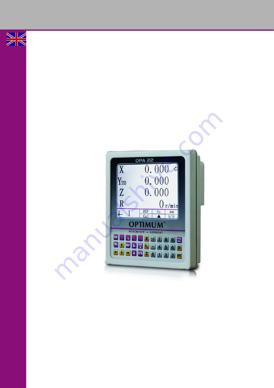
Digital position display
DPA 22
Page 1: ...GB OPTIMUM M A S C H I N E N G E R M A N Y Operating manual Version 1 0 Digital position display DPA 22...
Page 2: ...ntenance 12 2 6 6 Trouble shooting 13 2 7 Installation of ML measuring gibs 13 2 7 1 Assembly of the measurement gib housing 14 2 7 2 Assembly of the reading head 14 2 7 3 Trouble shooting 15 3 Operat...
Page 3: ...formation for its eco nomic operation as well as its long service life In the paragraph Maintenance all maintenance works and functional tests are described which the operator must perform in regular...
Page 4: ...ocessing and indicating position and rotational speed values Observe all safety instructions contained herein Arbitrary modifications and changes to this electronic display are forbidden Observe the p...
Page 5: ...l cause personal injury serious damage to machine or actuator Configuration commissioning mounting and maintenance by trained expert personnel only This personnel must be able to recognize danger that...
Page 6: ...d sensor without commercial permanent magnets as a signal transducer 2 2 Mechanical installation CAUTION Failure of electronic display When mounting pay attention to the IP type of protection Avoid im...
Page 7: ...of opera tion that excludes inductive or capacitive interference influences on the electronic display or its connecting lines When mounting the system keep a maximum possible distance from lines loade...
Page 8: ...s DPA22 GB 2 4 Power supply speed sensor Power is supplied via the rear jack plug Connect the sensor for speed measurement from the scope of delivery with the electronic display 2 5 Signal selection f...
Page 9: ...TTL differential TTL square wave signal We recommend the application of original measuring gibs and magnetic measuring systems from OPTIMUM If the digital display is to be operated with measuring devi...
Page 10: ...cleansing agents are e g ketones acetone or alcohols Messrs octite and 3M can both supply such cleansing liquid Make sure that the surface to be glued is dry and apply the stop with maximum pressure G...
Page 11: ...hly protected surroundings In less protected mounting places the strip may peel In such cases mounting methods as shown in Img 2 2 and Img 2 3 are more suitable Optimal protection can be achieved thro...
Page 12: ...sor must not touch the magnetic strip Img 2 6 Distance sensor magnetic strip Img 2 7 Max deviation Img 2 8 Installation of sensor 2 6 4 Necessary measures The sensor should be positioned well away fro...
Page 13: ...o a TTL signal 2 7 Installation of ML measuring gibs Plug pinout sine 11uApp NOTE The following statements describe the procedure for attachment of OPTIMUM ML type absolute measuring glass scales Plea...
Page 14: ...ring gauge with the sealing lips showing downward If possible place the reading head stationary in order to avoid damages of the connection lines by its movements 2 7 2 Assembly of the reading head Th...
Page 15: ...operation The value shown on the display does not correspond to the actual value because the parameter setting for the counting resolution is set improperly Factory settings on page 18 Reading head i...
Page 16: ...rating instructions DPA22 GB 3 Operation The device s display is in the default state when initially turned on 3 1 Parameter settings Press button for 3 seconds to access parameter settings Press the...
Page 17: ...y value is set on the display than the actual counting resolution the representational accuracy value will be shown accordingly Counting direction The measurement counting direction positive or negati...
Page 18: ...s on the number of output pulses per revolution of the transducer in use i e rotational speed disc The greater this value is the higher will be the resolution of the revolution speed The range of poss...
Page 19: ...oint For input of negative or positive signs For numeric entry For input of decimal places decimal point 7 Delete key To clear displayed value of a specific axis or give up the current operation 8 Ent...
Page 20: ...with double allocation Coordinate points along a diagonal line Addition Coordinate points along a diagonal line on page 23 Calculator function on page 22 18 Key with double allocation Coordinate poin...
Page 21: ...er settings The set reference mark values are now transferred to the axis display Example Setting the values After pressing the reference mark function the following values should be set 0 500 for the...
Page 22: ...utton to start the calculator The display shows The number field for the rotational speed indicator is used as input and result field Press the button to exit from the calculator function Keys with do...
Page 23: ...from parameter settings Using the arrow keys select the menu point and input the desired value Press the button to execute the function Press the button to exit from the function 3 6 1 Parameter meani...
Page 24: ...n to execute the function The display shows Press the button to query the individual coordinate points Positioning to coordinate points Press button to select the desired coordinate point The machine...
Page 25: ...c run counterclockwise Coordinate point 2 is located counterclockwise of coordinate point 1 Press button to access parameter settings Press the button again to exit from parameter settings Using the a...
Page 26: ...g the numeric keys and confirm with the key Number of coordinate points on the circle or arc Input the number of coordinate points using the numeric keys and confirm with the key Start angle Input the...
Page 27: ...ividual coordinate points Positioning to coordinate points Press button to select the desired coordinate point The machine axes will proceed until the positions on the selected coordinate plane read 0...
Page 28: ...s the button again to exit from parameter settings Using the arrow keys select the menu point and input the desired value Press the button to execute the function Press the button to exit from the fun...
Page 29: ...ute the function The display shows Positioning to a coordinate point on the inclined plane The machine axes will proceed until the positions of the selected coordinate plane read 0 000 INFORMATION Pre...
Page 30: ...rameter settings Press the button again to exit from parameter settings Using the arrow keys select the menu point and the second page and input the desired value Press the button to execute the funct...
Page 31: ...c keys 0 or 1 0 Machining of the arc from inside 1 Machining of the arc from outside Confirm with the key Milling tool diameter Input the milliing tool diameter using the numeric keys and confirm with...
Page 32: ...proceed until the positions on the selected coordinate plane read 0 000 Press the button to display the second point of the coordinate plane The machine axes will proceed until the positions on the s...
Page 33: ...INFORMATION The saving function for tool data only when the reference mark function is acti vated Reference marker function on page 21 Stored values remain saved even after loss of electric power Exa...
Page 34: ...he original proof of purchase is not presented we are not able to perform any services Defects resulting from the following circumstances are excluded from liability and warranty claims Using the prod...
Page 35: ...nts made of cardboard box can be chopped up and supplied to thewaste paper collection The films are made of polyethylene PE and the cushion parts are made of polystyrene PS These materials can be reus...
Page 36: ...disposed of at a central collection point for recycling Your contribution to the correct disposal of this product will protect the environment and the public health Incorrect disposal constitutes a r...
Page 37: ...nation DPA 22 Year of manufacture __ __ __ __ Digital position display for using on machine tools for path measurement in conjunction with magnetic sen sors or glass rulers which meet all the relevant...
Page 38: ...OPTIMUM M A S C H I N E N G E R M A N Y Original operating instructions DPA22 GB...