Optimum CNC Controller III Operating Manual Download Page 6

Description of the connection

OPTIMUM

M A S C H I N E N   -   G E R M A N Y

29 / 11 / 2006

Page 

6

Description of the connection  CNC Controller III and VI ; Version 2.0.1

 ©

 20
06

GB

6.1

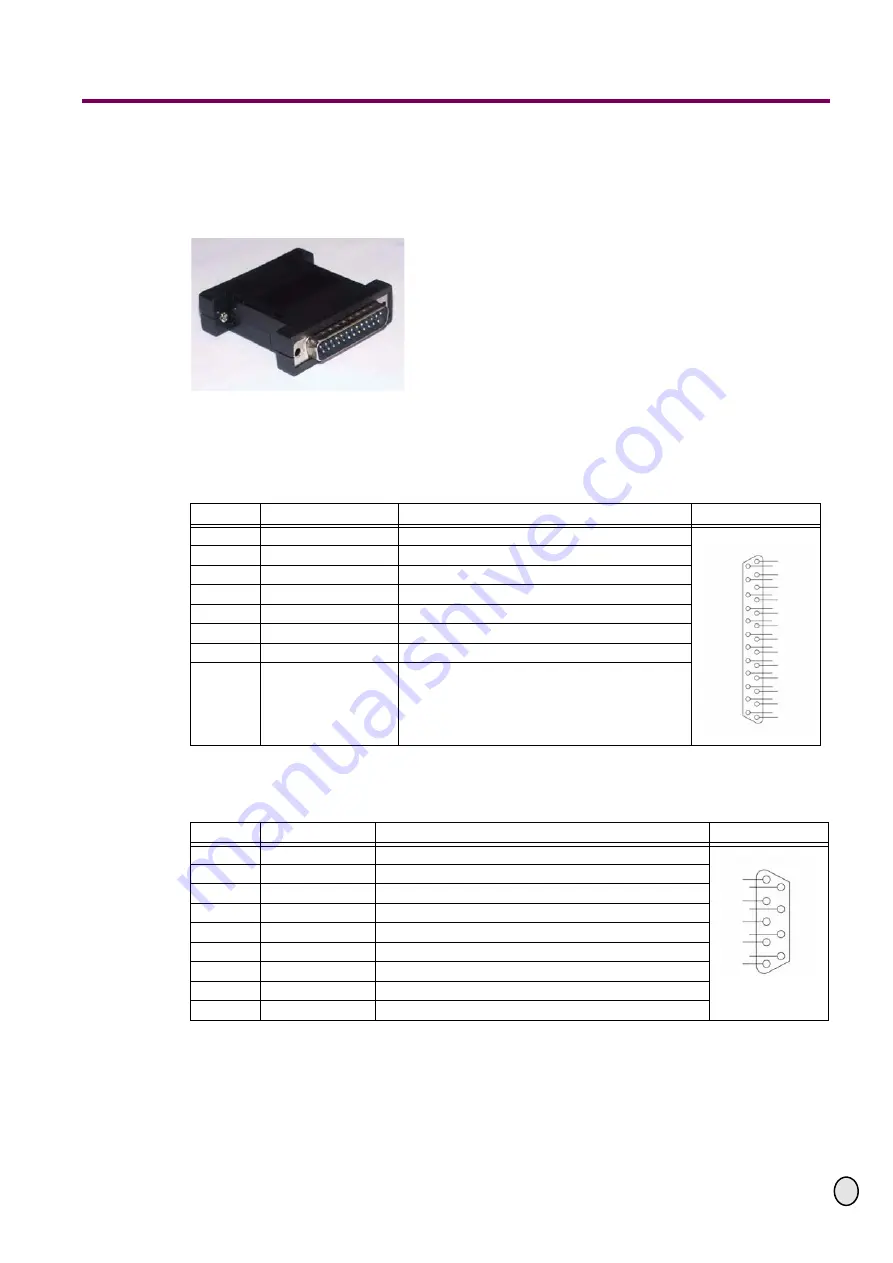
Signal configuration on the parallel port

The CNC controller III and VI need to be supplied with separate direction and cycle signals. 
When using the HSE software such as PCturn DOS PCturn for Windows you have to connect 
the adapter plug wihich is included in the delivery volume on the PC port.

Fig.6-1:   LPT port adapter plug

6.1.1

Assignment of the signals at the parallel port, CNC controller III (port / PC)

The following assignment of signals is required on the parallel port.

6.1.2

Assignment of signals at the port reference switch (Ref.switch)

The following signal configuration is used on the parallel port.

Pin No

Application

Description

DB 25 male

2

Direction X-axis

Direction signal to control the axis

3

Cycle X

Cycle signal to control the step motor

4

Direction Y

Direction signal to control the axis

5

Cycle Y

Cycle signal to control the step motor

6

Direction Z

Direction signal to control the axis

7

Cycle Z

Cycle signal to control the step motor

8 - 24

Free

Not assigned

25

OV DC, earthing

2
3
4
5
6
7
8

9
10

11
12

13

14
15

16
17
18
19
20
21
22
23
24

25

1

Pin No

Application

Description

DB9 female

1

X1

Machine point of origin port 1 X-axis

2

Y1

Machine point of origin port 1 Y-axis

3

Z1

Machine point of origin port 1 Z-axis

4

Round table

Point of origin round table port 1 

5

+12V DC

6

X2

Machine point of origin port 2 X-axis

7

Y2

Machine point of origin port 2 Y-axis

8

Z2

Machine point of origin port 2 Z-axis

9

0V  DC

5

4

3

2

9

8

7

6

1

Summary of Contents for CNC Controller III

Page 1: ...age 1 CNC Controller III and VI Version 2 0 1 2006 GB Img 0 1 CNC Controller III V2 Img 0 2 CNC Controller VI V2 Step motor control Half step operation CNC Controller III V2 CNC Controller VI V2 Versi...

Page 2: ...the signals at the parallel port CNC controller III port PC 6 6 1 2 Assignment of signals at the port reference switch Ref switch 6 6 1 3 Assignment of signals at the parallel port 1 CNC controller V...

Page 3: ...THIS DOCUMENTATION CLOSE TO THE CNC CONTROLLER 1 1 Proper use The CNC Controller is designed and built to be used in dry and non explosive environments It is provided to control step motors up to a m...

Page 4: ...red check immediately that the machine is not been damaged during transport and that all components are included Also check that no fastening screws have come loose 4 1 Delivery volume CNC controller...

Page 5: ...ned application in connection with Port 1 PC1 maximum 10 A X1 connection step motor X axis of the machine Port 2 relay potential free relay output for user defined application in connection with Port...

Page 6: ...itch The following signal configuration is used on the parallel port Pin No Application Description DB 25 male 2 Direction X axis Direction signal to control the axis 3 Cycle X Cycle signal to control...

Page 7: ...th axis Cycle signal of the optional 4th axis Optio nal 4th axis on parallel port 1 on page 8 10 Free Not assigned 11 Reference switch Z axis Assignment of signals at the port refe rence switch Ref sw...

Page 8: ...6 2 Front view CNC controller VI version 2 CAUTION When the 4th axis is activated only parallel port 1 can be used The parallel port 2 is switched off and can therefore not be used 6 1 6 Activating th...

Page 9: ...NC controllers of the ver sion 1 and 2 Control boards of the version 1 are not compatible to CNC controllers of the version 2 INFORMATION A CNC controller of the version 2 can be identified by the fol...

Page 10: ...ol board a control board has to be set as master control board the other control boards always as slave control boards The setting is performed over a jumper The master board is always exclusively in...

Page 11: ...be more power Please do not overturn the potentiometer Setting step motor 2 2 Nm about 75 Setting step motor 4 2 Nm about 100 Setting step motor 8 Nm about 100 When the red control lamp red LED is fla...

Page 12: ...g a control board a control board has to be set as master control board the other control board always as slave control boards The setting is performed over a jumper The master board is always exclusi...

Page 13: ...ed step motor over the jumper If the current is too high it will lead to a degradation of the running performances and does not perform more power J3 jumper 3 for step motor 3 A J4 jumper 4 for step m...

Page 14: ...Disconnect the mains plug and wait at least 3 minutes Disconnect the plug of the step motor from the control board Screw off the slot cover of the control boards Pull off the control board from the s...

Page 15: ...e screening INFORMATION The screening will be connected to the terminal block of the motor on one side The cable will be stripped at a length of about 5mm with insulation stripping tongs Plug and pres...

Page 16: ...er Connect the cable to the CNC controller as required Fig 8 6 Terminal strip CNC controller VI INFORMATION No screening and no grounding cable is connected to the CNC controller If the turning direct...

Page 17: ...ontrol board V2 on page 11 9 2 All axes are no longer triggered In case of a short circuit or excess voltage or in case of a defect on the control board all 3 axes will be switched off This way a dama...

Page 18: ...5027 Hauptplatine CNC Controller III Version 2 Mainboard CNC Controller III version 2 0357195028 Frontblende CNC Controller VI Front screen Front cover CNC Controller VI 035719509V2 Frontblende CNC Co...

Page 19: ...ges due to operator s mistakes may not be accepted as warranty claims Correct use of devices The products of the company Optimum had been designed and built for certain purposes They are listed in the...

Page 20: ...e environment and the health of your fellow men The environment and the health are endangered by incorrect disposal Recycling of material will help to reduce the consumption of raw materials Your Dist...

Page 21: ...ct Machine type CNC Controller Relevant EU directives EMV directive 89 336 EWG Low Voltage Directive 73 23 EWG meets the provisions of the aforementioned directive including any amendments valid at th...

Page 22: ...OPTIMUM M A S C H I N E N G E R M A N Y 29 11 2006 Page 22 CNC Controller III and VI Version 2 0 1 2006 GB...

Reviews: