iii
CHAPTER TITLE PAGE
1
OPR Power Series – Introduction …………………………..................... 1
1.1 Product
Description………………………………………………………… 1
1.2 Main
Features………………………………………………………………. 1
1.3
General OPR Power Series Specifications………………………………….
2
1.4 Typical
Safety
Rating………………………………………………………. 2
2
OPR300-24S / OPR300-24R………………………………………………
3
2.1
OPR300-24S / OPR300-24R Description…………………………………..
3
2.2 Specifications
…………………………………………………………….... 3
3
Status Indicators and Back Panel Connections………………………….
5
3.1
Back Panel DC Power Connector………………………………………….. 5
3.2
Front Panel Status Indicators…………………………………...................... 5
3.3
Remote Management DB-25 Connector Pin Out for OPR300-24S…………
5
3.4
Remote Management DB-25 Connector Pin Out for OPR300-24R…………
5
4 Alarm
Systems…………..………………………………………………….
6
4.1 Alarm
Monitoring
System………………………………………………….. 6
5
Installation and Maintenance………………………………...................... 7
5.1 Installation………………………………………………………………….. 7
5.2 Maintenance………………………………………………………………… 7
5.3 Warnings……………………………………………………….................... 8
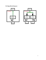
5.4 Design
Block
Diagram……………………………..…………..................... 9
6 Images….………………………………………………………………….. 10
6.1
OPR300-24S (Single Power Supply)…………………………..................... 10
6.2 OPR300-24R
(Redundant
Power
Supply)……………………..................... 10
6.3 OPR300-24R
(Front
View)……………………………………………….... 11
6.4
OPR300-24S (Front View)………………………………………………....
11
6.5 OPR300-24S
(Rear
View)…………………………………………………. 12
6.6
OPR300-24R (Rear View)…………………………………….................... 12
6.7 DC
Cable
Image…………………………………….................................... 13


