


Installation
Important: Please use the installation procedure below. Improper, or no
operation may result if the start-up sequence is not correctly followed.
Step 1
Carefully unpack the contents of the shipping group. Before next step, ensure
that your graphic card is set at no higher than SXGA (1,280x1,024) 60Hz in
direct connection of copper DVI cables.
Step 2
With system power turned
off
, connect the upstream Transmitter box to the
DVI and USB receptacle of a computer by a DVI and a USB copper cable,
respectively. Even without USB connection, this product works. If necessary,
the RS232 cable plugs to the D-sub 9-pin connector.
Figure 2 – Connection of DVI, USB, and RS232 cables between Transmitter box and a
computer
Step 3
In the same way as above, connect the Receiver box into the DVI receptacle
of the display, the USB devices and the RS232 device by the other DVI, USB,
and RS232 copper cables, respectively. The receiver offers a connection of 4
USB devices.
Figure 3 – Connection of DVI, USB, and RS232 cables between Receiver box and display
and devices
1-3 Installation
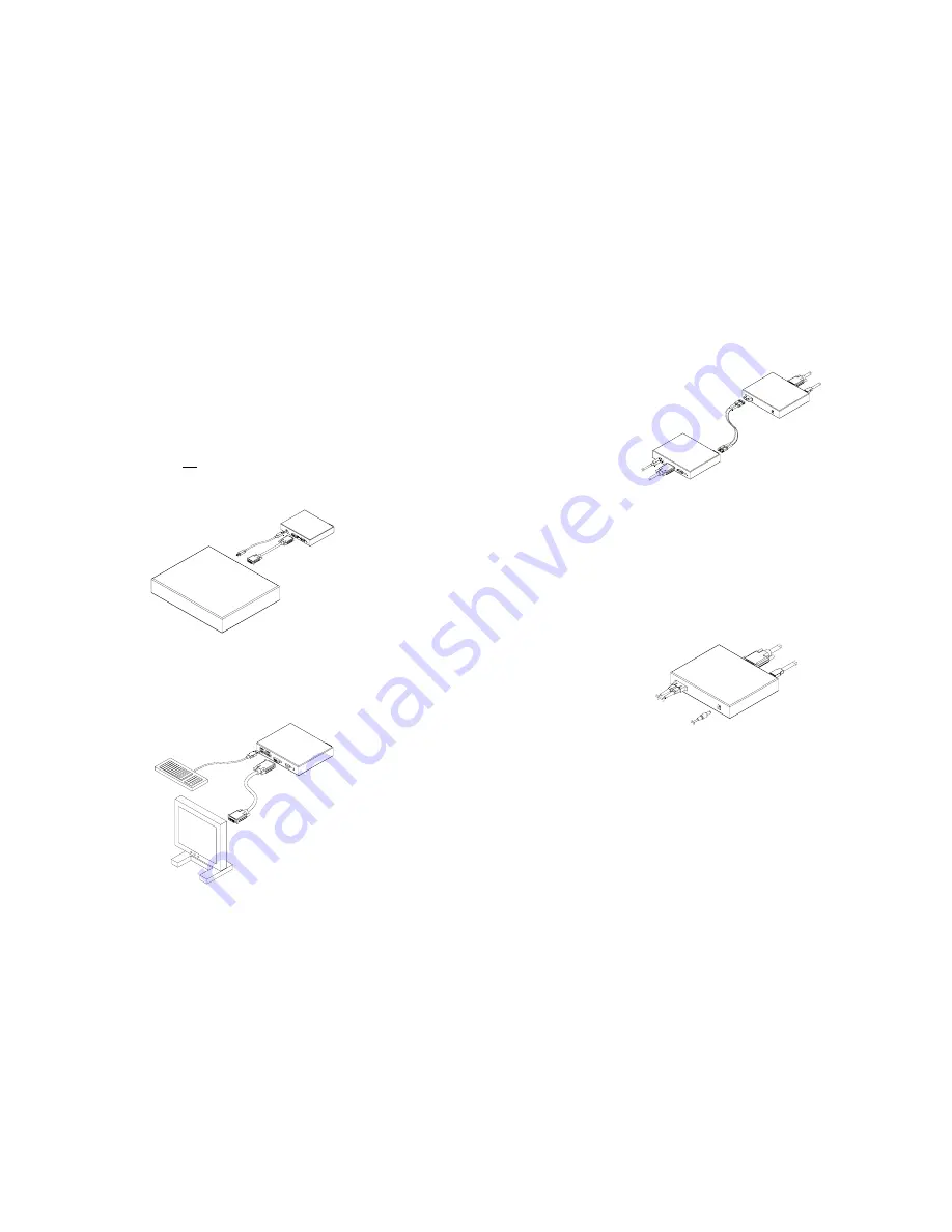
Step 4
Remove the module dust covers and connect a duplex SC fiber cable to SC
receptacles of the Transmitter and Receiver boxes, as shown in Fig. 4.
Carefully ensure the duplex connectors are fully engaged.
.
Figure 4 – Connection of duplex SC fiber cables
Notice:
Please DO NOT look directly into the SC receptacles of both
Transmitter and Receiver boxes, while they are powered on, although they
are regulated strictly enough to operate under the Laser Class I, classified by
CDRH/FDA for eye safety.
Step 5
Connect an AC/DC power adapter to both of the Transmitter and Receiver
boxes as your availability of AC outlets. You can find power indicators lit on in
the both boxes.
Figure 5 – Connection of AC/DC power adaptor
Step 6
Power on the computer and display or connected devices. Ensure the link
indicators are light on, presenting secure connection of SC duplex fiber cables
and the DVI indicator in the Transmitter box light on, presenting secure
connection of the DVI cable. You can find USB indicators being connected to
your USB devices.
Tip 1:
After initial installation as guided in the above, we recommend you to
power On and Off while all connections are set and the Tx/Rx boxes are
powered in.
Tip 2:
Avoid “hot plugging” the Tx or Rx boxes as this is not recommended
practice with live digital voltages.
1-4 Installation (continued)


