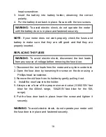
damage to the product.
MAX
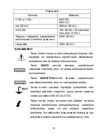
This symbol advises the user that the terminal(s) so
marked must not be connected to a circuit point at
which the voltage with respect to earth ground
exceeds (in this case) 500 VAC or VDC.
This symbol adjacent to one or more terminals
identifies them as being associated with ranges that
may, in normal use, be subjected to particularly
hazardous voltages. For maximum safety, the meter
and its test leads should not be handled when these
terminals are energized.
CONTROLS AND JACKS
1. 4000 count Liquid Crystal Display with symbolic signs
2. Function switch
3. 10A (positive) input
jack for 10A DC or AC
measurements
4. COM (negative) input jack
5. Positive input jack
6. MODE pushbutton
7. Range pushbutton
8. Data Hold/Back Light pushbutton
9. Relative pushbutton
10. Battery Cover
4
Summary of Contents for DT-916N
Page 1: ...1...
Page 122: ...Russian DT 916N z z z z 60 30 122...
Page 123: ...z z z 600 600 A 400 A A 10A 30 15 250 250 123...
Page 124: ...500 124 MAX...
Page 125: ...1 2 3 10A 10A 125 4 COM 5 6 MODE 7 8 9 10 DATA HOLD BAT AUTO AC DC EN61010 1 2 CATIII 600...
Page 127: ...127 1 30 2 OL MODE...
Page 128: ...128 1 RANGE AUTO 2 RANGE 3 RANGE DATA HOLD 1 DATA HOLD HOLD 2 DATA HOLD HOLD 1 HOLD HOLD...
Page 129: ...1 RELATIVE REL 2 3 RELATIVE 129 1 2 1...
Page 130: ...130 1 V DC 2 COM V 3 4...
Page 131: ...131 240 0 1 V AC 2 COM V 3 4...
Page 132: ...132 10 30 30 1 COM 2 4000 A A A 3 400 A A A 4 10A 10A 5 DC 6 7 8 9...
Page 133: ...133 250 10A 30 1 COM 2 4000 A A A 3 400 A A 4 10A 10 5 6 7 8 9...
Page 134: ...1 2 COM 3 4 1 2 COM 134...
Page 135: ...3 MODE 4 5 150 1 2 MODE 3 COM 4 5 6 A OL B OL C 0 135...
Page 136: ...1 FREQ 2 COM F 3 4 1 nF 2 COM CAP 136...
Page 137: ...137 3 1 TEMP 2 COM Temp 3 30 4 5...
Page 138: ...138 1 BAT 2 3 1 2 3...
Page 139: ...139 1 2 3 4 5 0 5A 250 400 A 10A 250 10A 6...
Page 140: ...140 140...


