background image


43 / 120 


ZE1000-3000_manual_ger_eng_it_V1.0.3

 ........................................................................ 

R. Kistler


Contents 

 
User Manual .................................................................................... 41


1.


Introduction ............................................................................... 46


2.


Safety warnings ........................................................................ 48


3.


Installation ................................................................................ 49


3.1


Inspecting the shipment .................................................... 49


3.2


Unpacking the UPS system .............................................. 49


3.3


Checking the accessories ................................................. 50


3.4


Installation as tower .......................................................... 50


3.5


Installation in the rack ....................................................... 51


3.6


Commissioning .................................................................. 53


4.


Operation .................................................................................. 54


4.1


Control panel ..................................................................... 54


4.2


Display ............................................................................... 55


4.3


Settings ............................................................................. 56


4.4


Operating states ................................................................ 58


4.5


Startup and shutdown ....................................................... 59


5.


Communication......................................................................... 61


5.1


RS-232 and USB interfaces .............................................. 61


5.2


Potential free contacts ....................................................... 62


5.3


Slot for interface cards ...................................................... 62


5.4


Emergency-off function (EPO) .......................................... 63


5.5


DataWatch software .......................................................... 64


5.6


USB for HID power device ................................................ 64


6.


Maintenance ............................................................................. 65


6.1


Care and maintenance ...................................................... 65


6.2


Storage .............................................................................. 65


6.3


Proper time to change the battery ..................................... 65


6.4


Battery change .................................................................. 66


6.5


Testing the new batteries .................................................. 69


6.6


Disposing of old batteries or the UPS system ................... 70


7.


Troubleshooting ........................................................................ 71


7.1


Warning messages............................................................ 71


7.2


General faults .................................................................... 72


7.3


Muting the alarm................................................................ 72


7.4


Support .............................................................................. 73


Summary of Contents for XANTO E 1000

Page 1: ...land Italien Schweiz ONLINE USV Systeme AG Luise Ullrich Str 8 D 82031 Grünwald Phone 49 89 2423990 10 Fax 49 89 2423990 20 www online usv de ONLINE UPS Systems S r l Via Ferruccio Gilera 110 I 20862 Arcore MB Phone 39 039 2051444 Fax 39 039 2051435 www online ups it ONLINE USV Systeme AG Eigenheimstraße 11 CH 8304 Wallisellen Zürich Phone 41 44 9452829 Fax 41 44 9453288 www online usv ch ...

Page 2: ...2 120 ZE1000 3000_manual_ger_eng_it_V1 0 3 R Kistler ...

Page 3: ...Betriebszustände 18 4 5 Starten und Abschalten 19 5 Kommunikation 21 5 1 RS 232 und USB Schnittstelle 21 5 2 Potenzialfreie Kontakte 22 5 3 Slot für Schnittstellenkarten 22 5 4 Notaus Funktion EPO 23 5 5 DataWatch Software 24 5 6 USB für HID Power Devices 24 6 Wartung 25 6 1 Pflege und Wartung 25 6 2 Lagerung 25 6 3 Zeitpunkt für den Batteriewechsel 25 6 4 Batteriewechsel 26 6 5 Testen der neuen B...

Page 4: ...4 120 ZE1000 3000_manual_ger_eng_it_V1 0 3 R Kistler 8 Technische Daten 34 8 1 Spezifikation 34 8 2 Rückansicht 35 8 3 CE Bestätigung 37 9 Garantie 38 ...

Page 5: ...ker 23 Abbildung 11 Entfernen der Frontblende 27 Abbildung 12 Trennen der Batterie Steckverbindung 28 Abbildung 13 Entfernen der Batterieabdeckung 28 Abbildung 14 Entnahme des Batterieeinschubes 28 Abbildung 15 Rückansicht ZINTO E 1000 35 Abbildung 16 Rückansicht ZINTO E 1500 und 2000 36 Abbildung 17 Rückansicht ZINTO E 3000 36 Tabellenverzeichnis Tabelle 1 Lieferumfang 10 Tabelle 2 Anzeigebeschre...

Page 6: ...omversorgung oft er heblichen Schwankungen unterliegen Netzprobleme können dazu führen dass kritische Daten zerstört werden ungesicherte Daten verloren gehen und Hardware beschädigt wird Teure Reparaturen und Ausfallstunden sind die Folge Ob preissensitiver Einstiegsserver oder Highend PC Telefonanlage Netzwerkperipherie oder NAS ZINTO E schützt sensible Anwen dungen vor Datenverlust und Betriebss...

Page 7: ...rad von 96 EBM Ladetechnologie für 72 Monate Batterielebenserwar tung Hot Swap Batterie Wechsel im laufenden Betrieb ohne Ab schalten der Verbraucher RS 232 und USB Schnittstelle Generator Kompatibilität Kaltstartfunktion Slot für optionalen SNMP Adapter nicht ZINTO E1000 Notaus Funktion EPO Emergency Power Off nicht ZINTO E1000 2 Jahre Garantie inkl Batterie Abbildung 2 ZINTO E 1000 3000 im Rack ...

Page 8: ...bäuden mit kontrollierter Temperatur und Luftfeuchtigkeit installiert wer den in denen keine leitenden Schmutzstoffe vorhanden sind Die Umgebungstemperatur darf 40 C nicht übersteigen Die USV Anlage darf nicht in der Nähe von Wasser oder in ex trem hoher Luftfeuchtigkeit 80 betrieben werden Vergewissern Sie sich vor dem Transport der USV Anlage dass die USV Anlage von der Stromversorgung getrennt ...

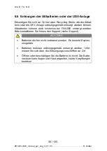
Page 9: ...rd kann es zu Kondensatbildung innerhalb und außerhalb des Gehäuses kommen Installieren Sie die USV Anlage nur wenn Innen und Außenseite vollständig trocken sind Gefahr eines elektrischen Schlages Die USV Anlage hat ein hohes Gewicht siehe Technische Daten Vorsicht beim Auspacken und Transportieren der USV HINWEIS Bewegen und öffnen Sie die verpackte USV Anlage vorsich tig Lassen Sie die Komponent...

Page 10: ...INTO E 3000 Software DataWatch 1 Bedienungsanleitung 1 Tabelle 1 Lieferumfang 3 4 Installation als Tower Die USV Anlage wird vollständig zusammengebaut und anschluss fertig geliefert ACHTUNG Das Gehäuse hat ein hohes Gewicht siehe Technische Daten 1 Schieben Sie die USV Anlage vertikal in die beiden Füße siehe Abbildung 4 Achten Sie auf einen möglichst großen Abstand zwi schen den Füßen um hohe St...

Page 11: ...blende siehe Abbildung 5 Lösen Sie zuerst die beiden Schrauben an der rechten Seite der Blende Schieben Sie danach die Blende nach links Abbildung 5 Entfernen der Frontblende 3 Drücken Sie die Plastikklammern auseinander und ziehen Sie das Display aus der Befestigung Drehen Sie es gegen den Uhrzeigersinn um 90 Grad und stecken Sie es wieder in der Frontblende 4 Setzen Sie die Frontblende wieder ei...

Page 12: ...n Schraubenbohrungen auf jeder Seite der USV Anlage aus und befestigen Sie diese mit den beigefügten M4 x 8 Flach kopfschrauben 7 Schieben Sie die USV Anlage in das Rack 8 Befestigen Sie die Montagewinkel der USV Anlage am Rack siehe Abbildung 6 Abbildung 6 Befestigung im Rack 9 Fahren Sie mit dem Abschnitt Inbetriebnahme fort ...

Page 13: ...tet beheben Sie alle Warnmel dungen und starten Sie die USV Anlage ggfs neu siehe Fehlerbehebung 5 Vergewissern Sie sich dass im Display NORM angezeigt wird Dadurch wird signalisiert dass die USV Anlage im Nor malbetrieb arbeitet und die Verbraucher mit Strom versorgt werden HINWEIS Beim ersten Starten wird die Ausgangsfrequenz auf den Wert der Eingangsfrequenz gesetzt die automatische Er kennung ...

Page 14: ...ngangsspannung trennen und Taste länger als 3s gedrückt halten Funktionstest Taste länger als 3s gedrückt halten Batterietest Taste länger als 10s gedrückt halten Alarmsignal AUS Taste kurz drücken Scrollen Taste kurz drücken Einstellmodus auswählen Taste länger als 3s gedrückt halten Einstellung auswählen Taste länger als 1s gedrückt halten Einstellung bestätigen Taste länger als 1s gedrückt halt...

Page 15: ...n USV Status Zeigt den USV Status an Siehe Tabelle 4 Warnmeldung Leuchtet auf wenn Warnmeldung vorliegt Siehe Warnmeldungen Einstellungen Leuchtet auf wenn Menü Einstellungen akti viert ist Siehe Einstellungen Batterieanzeige Zeigt die aktuelle Kapazität der Batterie an Jedes Segment entspricht 20 Wenn alle Segmente leuchten ist die Batterie zu 100 geladen Lastanzeige Zeigt die aktuelle Last an Je...

Page 16: ...Kurzschluss am Ausgang der USV Anlage OVLD Überlast am Ausgang der USV Anlage bATH Batteriespannung zu hoch bATL Batteriespannung zu niedrig OVTP Interne Temperatur zu hoch FNLK Lüfter blockiert bTWK Batterien schwach Tabelle 4 Übersicht Betriebsstatus 4 3 Einstellungen 1 Einstellungsmodus auswählen Taste 3s gedrückt halten 2 Scrollen zwischen den Einstellungen Taste drücken bis gewünschte Einstel...

Page 17: ...ngstoleranz 002 Generator 40Hz 70Hz Eingangsfrequenztoleranz Normal TEST Automatische Selbsttests 000 deaktiviert 001 aktiviert aktiviert AR Automatischer Neustart 000 deaktiviert 001 aktiviert aktiviert bZ Alarm 000 deaktiviert 001 aktiviert aktiviert LS1 Lastsegment 1 nicht ZINTO E 1000 000 ausgeschaltet 001 eingeschaltet einge schaltet LS2 Lastsegment 2 nicht ZINTO E 1000 000 ausgeschaltet 001 ...

Page 18: ... werden über die Batterie mit Strom versorgt Ist der Batterieladezustand im Batteriebetrieb niedrig wird im Display bATL angezeigt und der Alarm ertönte jede Sekunde Die verblei bende Überbrückungszeit ist gering Schließen Sie alle Anwendun gen da die automatische Abschaltung der USV Anlage kurz bevor steht Ist der Batterie im Batteriebetrieb erschöpft schaltet sich die USV Anlage ab Alle Anzeigen...

Page 19: ...n Sie sich dass im Display NORM angezeigt wird Die USV Anlage arbeitet im Normalbetrieb und versorgt die Verbraucher mit Strom Starten im Batteriebetrieb HINWEIS Um die Ausgangsfrequenz von 50 oder 60Hz zu aktivieren muss die USV Anlage vor der erstmaligen Verwendung des Batteriebetriebs mindestens einmal vom Netz versorgt und gestartet worden sein 1 Halten Sie die Taste an der USV Anlage gedrückt...

Page 20: ...s Signal Die USV Anlage wechselt in den Standby Betrieb und das Display zeigt STbY an HINWEIS Wird die Taste nach weniger als drei Sekunden losgelas sen so kehrt die USV Anlage wieder zu ihrer vorherigen Be triebsart zurück 2 Ziehen Sie das Netzanschlusskabel der USV Anlage aus der Steckdose Das Display der USV Anlage erlischt nach kurzer Zeit und die USV Anlage schaltet sich komplett aus ...

Page 21: ...rden Danach kann die USV Anlage Daten über die DataWatch Software siehe DataWatch Software austauschen Mittels USB Protokoll besteht auch die Möglichkeit des direkten Datenaustauschs ohne Softwareinstallation siehe USB für HID Power Device Die Belegung der Kabelanschlussstifte für die RS 232 Kommuni kationsschnittstelle ist in Abbildung 8 dargestellt die Funktionen der Anschlussstifte entnehmen Si...

Page 22: ...okoppler können nur kleine Ströme max 70mA schalten Wird eine Last mit höherem Stromverbrauch angeschlossen muss ein Relais zwischen Optokoppler und Last geschaltet werden 5 3 Slot für Schnittstellenkarten Die ZINTO E nicht ZINTO E 1000 ist mit einem Slot siehe Abbil dung 16 und Abbildung 17 für die folgenden Schnittstellenkarten ausgestattet Art Nr Beschreibung DW7SNMP30 SNMP Adapter Basic Der SN...

Page 23: ...ie mit dem Versorgungsnetz verbunden sind Eine verstärkte Isolierung zum Netz ist erforderlich Der Notaus Schalter muss mindestens für 24V und 20mA ausge legt sein Es muss ein Öffner verwendet werden Für den ordnungsgemäßen Betrieb muss die Notaus Funktion min destens 250ms lang aktiv bleiben Wenn die die Notaus Funktion aktiviert wird muss zusätzlich die Eingangsspannung der USV Anlage unterbroch...

Page 24: ...us verfügt DataWatch über ein umfangrei ches Messaging System zeitgesteuerte Testroutinen sowie eine Er eignisprotokollierung DataWatch unterstützt alle aktuellen Betriebssysteme Als Client Server Anwendung arbeitet DataWatch in Netzwerken und auf lokalen Workstations Mittels optionalem RCCMD Agent Remote Console Command lassen sich mehrere an einer USV Anlage angeschlossene Server ohne zusätzlich...

Page 25: ...ach Ablauf der zu erwartenden Lebensdauer haben weiter verwendete Batte rien häufig deutlich verringerte Laufzeiten Tauschen Sie die Batterien rechtzeitig aus damit die Anlage immer mit optima ler Leistung laufen kann 6 2 Lagerung Falls Sie die USV Anlage über längere Zeit lagern laden Sie die Bat terie alle sechs Monate auf indem Sie die USV Anlage an das Ver sorgungsnetz anschließen Die internen...

Page 26: ...rtraut ist Halten Sie unbefugtes Personal von den Batterien fern Batterien bergen das Risiko eines elektrischen Schlags oder einer Verletzung durch hohe Kurzschlussströme Halten Sie folgende Sicherheitsvorkehrungen ein o Nehmen Sie Uhren Schmuck und andere Metallgegen stände ab o Verwenden Sie nur Werkzeug mit isolierten Griffen o Legen Sie Werkzeuge oder Metallteile nicht auf den Bat terien ab Di...

Page 27: ...in hohes Gewicht Beim Umgang mit den schweren Batterien ist Vorsicht gebo ten Die Batterien befinden sich hinter der Frontblende der USV Anlage Die internen Batterien sind wegen der besseren Handhabung zu sammen verpackt 1 Entfernen Sie die Frontblende siehe Abbildung 11 Lösen Sie zuerst die beiden Schrauben an der rechten Seite der Blende Schieben Sie danach die Blende nach links Abbildung 11 Ent...

Page 28: ...rbindung siehe Abbildung 12 Abbildung 12 Trennen der Batterie Steckverbindung 3 Entfernen Sie die Batterieabdeckung siehe Abbildung 13 Abbildung 13 Entfernen der Batterieabdeckung 4 Ziehen Sie den Batterieeinschub vorsichtig am Griff heraus siehe Abbildung 14 Abbildung 14 Entnahme des Batterieeinschubes ...

Page 29: ...nicht zur Gefährdung von Personen führen Führen Sie das Kabel der Batterien schnell und kräftig in die Batterie Steckverbindung der USV Anlage ein 7 Fahren Sie mit dem Abschnitt Testen der neuen Batterien fort 6 5 Testen der neuen Batterien 1 Schließen Sie die USV Anlage zum Aufladen der Batterien für 48 Stunden an das Versorgungsnetz an 2 Halten Sie die Taste 10s lang gedrückt um den Batterie tes...

Page 30: ...rden können Altbatterien können auch kostenlos bei ONLINE entsorgt werden Bitte kontaktieren Sie hierzu den Support siehe Support ACHTUNG Batterien dürfen nicht verbrannt werden Es besteht Explosi onsgefahr Batterien müssen ordnungsgemäß entsorgt werden Infor mieren Sie sich über die Entsorgungsvorschriften vor Ort Öffnen oder beschädigen Sie die Batterie n nicht Die Batte riesäure kann Augen und ...

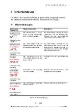
Page 31: ...betrieb Rotes Display bATL akustisches Sig nal jede s Die USV Anlage läuft im Batteriebetrieb und der Bat terieladestand ist niedrig Die USV Anlage versorgt die an geschlossene Last nur noch kurz mit Batteriestrom Bereiten Sie die an geschlossene Last auf das unmittel bare Herunterfahren vor Überlast Rotes Display OVLD akustisches Sig nal jede s Die Ausgangsleistung der USV Anlage wird überschrit ...

Page 32: ...r ist aktiv oder der EPO Anschluss fehlt Überprüfen Sie den Notaus Anschluss Die USV Anlage läuft im Normalbe trieb aber einige oder alle Verbrau cher sind nicht ein geschaltet Die Verbraucher sind nicht richtig an die USV Anlage angeschlossen Überprüfen Sie ob die Verbraucher mit den Anschlüssen der USV Anlage verbunden sind Der Batterietest wurde nicht ausge führt oder unter brochen Eine der unt...

Page 33: ...nach dem Kauf Bei ONLINE werden umfassende Support und Serviceleistungen groß geschrieben Direkte Beratung und Support kostenlos unter Software Hotline 49 89 242 39 90 13 Hardware Hotline 49 89 242 39 90 18 Kostenloser 24h Vorabaustausch Interaktiver USV Konfigurator im Internet oder als App 2 Jahre Vollgarantie optionale Verlängerung Unbürokratische 14 Tage Geld zurück Garantie Hohe Warenverfügba...

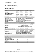
Page 34: ... Ausgangsspannung und frequenz 230V 5 Einstellbar auf 220V 230V 240V Normalbetrieb 50 60Hz 5Hz Batteriebetrieb 50 60Hz 0 1Hz Anschlüsse Eingang 1x IEC320 C14 10A 1x IEC320 C20 16A Ausgänge 8x IEC320 C13 10A zus 1x IEC320 C19 16A bei ZINTO E 3000 Batterien Typ Überbrückungszeiten bei 50 bzw 100 Last und pf 0 7 23 10min 20 9min 14 6min 14 6min Batterietyp 3x 12V 9Ah 4x 12V 9Ah 4x 12V 9Ah 6x 12V 9Ah ...

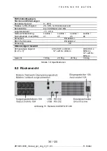
Page 35: ...00 Meter über NN Lagertemperatur 15 45 C Geräuschentwicklung Normalbetrieb max dBA Lautlos 41 Lautlos 45 Lautlos 45 Lautlos 48 Sicherheit EN 62040 1 EMV Performance EN 62040 2 Zulassung CE Abmessungen Gewicht Abmessungen liegend B x H x T 438 x 86 5 x 436mm 19 x 2HE x 436mm 438 x 86 5 x 605mm 19 x 2HE x 605mm Gewicht 16 6kg 20 5kg 20 5kg 30 4kg Tabelle 10 Spezifikationen 8 2 Rückansicht Abbildung ...

Page 36: ... D A T E N 36 120 ZE1000 3000_manual_ger_eng_it_V1 0 3 R Kistler HINWEIS Die Anschlüsse für Lastsegment 1 sind schraffiert darge stellt Abbildung 16 Rückansicht ZINTO E 1500 und 2000 Abbildung 17 Rückansicht ZINTO E 3000 ...

Page 37: ...T E C H N I S C H E D A T E N 37 120 ZE1000 3000_manual_ger_eng_it_V1 0 3 R Kistler 8 3 CE Bestätigung ...

Page 38: ...Von hierin vorgesehenen Ausnahmen abgesehen übernimmt ONLINE keinerlei ausdrückliche oder stillschweigende Garantie ein schließlich der Zusicherung handelsüblicher Qualität oder der Eig nung für einen bestimmten Zweck In einigen Gerichtsbarkeiten ist die Einschränkung oder der Ausschluss stillschweigender Garantien untersagt so dass die vorstehenden Einschränkungen oder Aus schlüsse für den Käufer...

Page 39: ...39 120 ZE1000 3000_manual_ger_eng_it_V1 0 3 R Kistler ...

Page 40: ...40 120 ZE1000 3000_manual_ger_eng_it_V1 0 3 R Kistler ...

Page 41: ...Italy Switzerland ONLINE USV Systeme AG Luise Ullrich Str 8 D 82031 Grünwald Phone 49 89 2423990 10 Fax 49 89 2423990 20 www online usv de ONLINE UPS Systems S r l Via Ferruccio Gilera 110 I 20862 Arcore MB Phone 39 039 2051444 Fax 39 039 2051435 www online ups it ONLINE USV Systeme AG Eigenheimstraße 11 CH 8304 Wallisellen Zürich Phone 41 44 9452829 Fax 41 44 9453288 www online usv de ...

Page 42: ...42 120 ZE1000 3000_manual_ger_eng_it_V1 0 3 R Kistler ...

Page 43: ... 56 4 4 Operating states 58 4 5 Startup and shutdown 59 5 Communication 61 5 1 RS 232 and USB interfaces 61 5 2 Potential free contacts 62 5 3 Slot for interface cards 62 5 4 Emergency off function EPO 63 5 5 DataWatch software 64 5 6 USB for HID power device 64 6 Maintenance 65 6 1 Care and maintenance 65 6 2 Storage 65 6 3 Proper time to change the battery 65 6 4 Battery change 66 6 5 Testing th...

Page 44: ...44 120 ZE1000 3000_manual_ger_eng_it_V1 0 3 R Kistler 8 Technical Data 74 8 1 Specification 74 8 2 Rear view 75 8 3 CE conformity 77 9 Warranty 78 ...

Page 45: ...re 10 EPO plug 63 Figure 11 Removing the front cover 67 Figure 12 Disconnecting the battery plug connection 68 Figure 13 Removing the battery cover 68 Figure 14 Removing the battery module insert 68 Figure 15 Rear view of ZINTO E 1000 75 Figure 16 Rear view of ZINTO E 1500 and 2000 76 Figure 17 Rear view of ZINTO E 3000 76 List of tables Table 1 Package 50 Table 2 Display descriptions 54 Table 3 D...

Page 46: ... also often subject to considerable fluctuations Mains problems can lead to critical data being destroyed unsecured data being lost and hardware being damaged Expensive repairs and downtimes are the result Whether expensive entry servers or high end PCs telephone sys tems network periphery or NAS ZINTO E protect sensitive applica tions against data loss and downtimes Two of the many highlights of ...

Page 47: ...96 efficiency EBM charging technology for expected 72 month battery ser vice life Hot swap battery Change during operation without deactiva tion of the consumers RS232 and USB interfaces Generator compatibility Cold start function Slot for optional SNMP adapter not ZINTO E1000 Emergency off function EPO Emergency Power Off not ZINTO E1000 2 year guarantee including battery Figure 2 ZINTO E 1000 30...

Page 48: ... shock the UPS sys tem may only be installed in buildings with controlled tem perature and air humidity in which there are no conducting contaminants present The ambient temperature may not rise above 40 C The UPS system must not be operated near water or in extremely high humidity 80 Make sure that the UPS system is switched off and discon nected from the power supply before transporting the UPS ...

Page 49: ...ient tempera tures condensation may form on the outside and inside of the housing Install the UPS system only when the inside and outside are completely dry risk of an electric shock The UPS system is heavy see Technical Data Use caution when unpacking and transporting the UPS system NOTE Move and open the packaged UPS system carefully Leave the components in the packaging until these are installe...

Page 50: ...0 2 ZINTO E 3000 16A power cable 1 only ZINTO E 3000 DataWatch software 1 Operating instructions 1 Table 1 Package 3 4 Installation as tower The UPS system is delivered completely assembled and ready to connect CAUTION The housing is heavy see Technical Data 1 Push the UPS system vertically into both ba ses see Figure 4 Pay attention to the largest possible distance be tween the bases to guarantee...

Page 51: ...rack kit see separate installation instruc tions 2 Remove the front cover see Figure 5 First loosen both screws on the right side of the cover Then push the cover to the left Figure 5 Removing the front cover 3 Press apart the plastic clamps and pull display out of the at tachment Rotate it counter clockwise by 90 degrees and rein sert it into the front cover 4 Insert the front cover again Slide t...

Page 52: ... L left and R right with the screw holes on each side of the UPS system and secure these using the supplied M4 x 8 pan head screws 7 Push the UPS system into the rack 8 Attach the mounting bracket of the UPS system to the rack see Figure 6 Figure 6 Fastening in rack 9 Proceed with the Commissioning section ...

Page 53: ... all warning messages and restart the UPS system if necessary See Troubleshooting 5 Make sure that NORM is displayed on the display This indi cates that the UPS system is working in normal mode and the consumers are being provided with power NOTE When starting for the first time the output frequency is set to the value of the input frequency the automatic detection is enabled by default 6 If an ad...

Page 54: ...on in case of error Disconnect the line input voltage and press the button longer than 3 seconds Function test Press the button longer than 3 seconds Battery test Press the button longer than 10 sec onds Alarm signal OFF Press the button briefly Scroll Press the button briefly Select setup mode Press the button longer than 3 seconds Select setting Press the button longer than 1 second Confirm sett...

Page 55: ... the line output jack UPS status Indicates the UPS status See Table 4 Warning mes sage Lights up when a warning message is pre sent See Warning messages Settings Lights up when the Settings menu is acti vated See Settings Battery display Shows the current battery capacity Every segment corresponds with 20 If all seg ments light up the battery is completely charged Load display Displays the current...

Page 56: ...ST Short circuit at output of the UPS system OVLD Overload at output of the UPS system bATH Battery voltage too high bATL Battery voltage too low OVTP Internal temperature too high FNLK Fan blocked bTWK Batteries weak Table 4 Operating status overview 4 3 Settings 1 Select the settings mode Keep the button pressed for 3 seconds 2 Scroll between the settings Press the button until the de sired sett...

Page 57: ...e range 20 30 line input voltage tolerance 002 generator 40Hz 70Hz line input frequency tolerance Normal TEST Automatic self tests 000 disabled 001 enabled Enabled AR Automatic re start 000 disabled 001 enabled Enabled bZ Alarm 000 disabled 001 enabled Enabled LS1 Load segment 1 not ZINTO E 1000 000 deactivated 001 activated Activated LS2 Load segment 2 not ZINTO E 1000 000 deactivated 001 activat...

Page 58: ...he connected consumers are supplied with power through the battery If the battery charge state is low in battery mode bATL appears in the display and the alarm sounds every second The remaining delay time is brief Close all applications since the automatic deactivation of the UPS system is about to take place If the battery charge state is empty during battery operation the UPS system switches off...

Page 59: ...g 4 Make sure that NORM is displayed on the display The UPS system works in normal mode and supplies the consumers with power Startup in battery mode NOTE To activate the output frequency of 50 or 60Hz the UPS sys tem must be supplied from the power supply and started at least once before the first use of the battery mode 1 Keep the button on the UPS system pressed until the dis play lights up The...

Page 60: ... a brief acoustic signal The UPS sys tem switches to standby mode and the display shows STbY NOTE If the button is released after less than 3 seconds the UPS system will return to its previous operating mode 2 Remove the power cable of the UPS system from the socket The display of the UPS system goes out after a short time and the UPS system shuts down completely ...

Page 61: ...er that the UPS system can exchange data via the DataWatch software see DataWatch software Using the USB protocol it is also possible to exchange data directly without installing software see USB for HID power device The assignment of the cable connection pins for the RS 232 com munications port is shown in Figure 8 refer to Table 6 for the func tions of the connection pins Figure 8 RS232 interfac...

Page 62: ...pler circuit Optical couplers can be switched only at low currents max 70mA If a load with a higher current consumption is connected a relay must be switched between the optical coupler and the load 5 3 Slot for interface cards ZINTO E not ZINTO E 1000 is equipped with one slot see Figure 16 and Figure 17 for the following interface cards Art no Description DW7SNMP30 SNMP Adapter Basic The SNMP ad...

Page 63: ...to circuits that are connected with the mains power supply network A reinforced insulation to the mains is required the emergency off switch must be dimensioned for at least 24 V and 20 mA An opening contact must be used For proper operation the emergency off function must remain active for at least 250 ms If the emergency off function is activated the input voltage of the UPS system must addition...

Page 64: ...urable shutdown routine DataWatch also includes a comprehensive messaging system scheduled test routines and event logging DataWatch supports all current operating systems As client server application DataWatch works in networks and on lo cal workstations Using the optional RCCMD agent Remote Console Command multiple servers connected to a UPS system can be ac tivated and controlled via the networ...

Page 65: ...cy of use and ambient temperature After expira tion of the expected service life batteries which continue to be used frequently have reduced running times Exchange the batteries regularly so that the system is always running at optimum performance 6 2 Storage If you store the UPS system over a longer period of time charge the batteries every six months by connecting the UPS system to the mains pow...

Page 66: ... batteries and un derstands the necessary safety precautions Keep unauthor ised personnel away from batteries Batteries can pose a risk of electric shock or injury due to high short circuits currents Comply with the following safety precautions o Remove watches jewellery and other metal objects from your body o Use only tools with insulated grips and handles o Do not place tools or metal parts on ...

Page 67: ...eries of the UPS system are heavy Use caution when handling the heavy batteries The batteries are located behind the front cover of the UPS system For better handling the internal batteries are packaged together 1 Remove the front cover see Figure 11 First loosen both screws on the right side of the cover Then push the cover to the left Figure 11 Removing the front cover NOTE A ribbon cable connec...

Page 68: ...the battery plug connection see Figure 12 Figure 12 Disconnecting the battery plug connection 3 Remove the battery cover see Figure 13 Figure 13 Removing the battery cover 4 Carefully pull out the battery module insert by the handle see Figure 14 Figure 14 Removing the battery module insert ...

Page 69: ... system This is normal and does not pose a hazard to people Quickly and firmly insert the cable of the batteries into the battery plug connection of the UPS system 7 Proceed with section Testing the new batteries 6 5 Testing the new batteries 1 Connect the UPS system to the mains power for 48 hours to charge up the batteries 2 Press the button for 10 seconds to start the battery test TEST appears ...

Page 70: ...ies or UPS system properly You can also dispose of old batteries at ONLINE at no cost Please contact support for this option see Support CAUTION Batteries may not be incinerated There is a risk of explosion Batteries must be disposed of properly Inform yourself about the local disposal regulations Do not open or damage the batteries The battery acid can attack the eyes and skin as well as cause po...

Page 71: ... Battery mode Red display bATL Audio signal eve ry second The UPS system is running in battery mode and the bat tery charge state is low The UPS system supplies the con nected load with battery current only briefly Prepare the connected load for the immediate shutdown Overload Red display OVLD Audio signal eve ry second The output power of the UPS system has been ex ceeded 105 Reduce the connected...

Page 72: ... off switch EPO switch is active or the EPO connection is missing Check the emergency off connec tion The UPS system runs in normal mode however several or all con sumers are not switched on The consumers are not properly connected to the UPS system Check whether the consumers are connected with the connections of the UPS system The battery test was not performed or was interrupted One of the cond...

Page 73: ...se At ONLINE comprehensive support and service solutions are our top priority Direct consulting and support free of cost under Software hotline 49 89 242 39 90 13 Hardware hotline 49 89 242 39 90 18 Free 24 hour advanced replacement Interactive UPS configurator on the Internet or as app 2 years factory warrantee optional extension Hassel free 14 day money back guarantee High availability of goods ...

Page 74: ...tput voltage and frequency 230V 5 adjustable to 220V 230V 240V Normal mode 50 60Hz 5Hz Battery mode 50 60Hz 0 1Hz Connections Line input 1x IEC320 C14 10A 1x IEC320 C20 16A Line outputs 8x IEC320 C13 10A additionally 1x IEC320 C19 16A for ZINTO E 3000 Batteries Typ delay times at 50 or 100 load and pf 0 7 23 10min 20 9min 14 6min 14 6min Battery type 3x 12V 9Ah 4x 12V 9Ah 4x 12V 9Ah 6x 12V 9Ah Des...

Page 75: ... metres above sea level Storage temperature 15 45 C Noise development Normal mode max dBA silently 41 silently 45 silently 45 silently 48 Safety EN 62040 1 EMC performance EN 62040 2 Approval CE Dimensions weight Dimensions reclining W x H x TD 438 x 86 5 x 436mm 19 x 2HE x 436mm 438 x 86 5 x 605mm 19 x 2HE x 605mm Weight 16 6kg 20 5kg 20 5kg 30 4kg Table 10 Specifications 8 2 Rear view Figure 15 ...

Page 76: ...N I C A L D A T A 76 120 ZE1000 3000_manual_ger_eng_it_V1 0 3 R Kistler NOTE The connections for load segment 1 are shown shaded Figure 16 Rear view of ZINTO E 1500 and 2000 Figure 17 Rear view of ZINTO E 3000 ...

Page 77: ...T E C H N I C A L D A T A 77 120 ZE1000 3000_manual_ger_eng_it_V1 0 3 R Kistler 8 3 CE conformity ...

Page 78: ...een changed or modified in any way Save where explicitly provided otherwise ONLINE does not make any warranty express or implied including warranties as to quality or suitability for a specific purpose The laws of some jurisdictions do not allow the exclusion of implied warranties or limitations so that the existing restrictions or exclusions may possibly not apply to the purchaser Except as may b...

Page 79: ...79 120 ZE1000 3000_manual_ger_eng_it_V1 0 3 R Kistler ...

Page 80: ...80 120 ZE1000 3000_manual_ger_eng_it_V1 0 3 R Kistler ...

Page 81: ...nia Italia Svizzera ONLINE USV Systeme AG Luise Ullrich Str 8 D 82031 Grünwald Phone 49 89 2423990 10 Fax 49 89 2423990 20 www online usv de ONLINE UPS Systems S r l Via Ferruccio Gilera 110 I 20862 Arcore MB Telefono 39 039 2051444 Fax 39 039 2051435 www online ups it ONLINE USV Systeme AG Eigenheimstraße 11 CH 8304 Wallisellen Zürich Phone 41 44 9452829 Fax 41 44 9453288 www online usv ch ...

Page 82: ...82 120 ZE1000 3000_manual_ger_eng_it_V1 0 3 R Kistler ...

Page 83: ... Comunicazione 101 5 1 Interfaccia RS 232 e interfaccia USB 101 5 2 Contatti privi di potenziale 102 5 3 Slot per schede d interfaccia 102 5 4 Funzione arresto di emergenza EPO 103 5 5 Software DataWatch 104 5 6 USB per HID Power Devices 104 6 Manutenzione 105 6 1 Cura e manutenzione dell UPS e delle batterie 105 6 2 Immagazzinamento degli UPS batterie 105 6 3 Sostituzione delle batterie 105 6 4 S...

Page 84: ...84 120 ZE1000 3000_manual_ger_eng_it_V1 0 3 R Kistler 8 Dati tecnici 114 8 1 Specifiche dei sistemi UPS 114 8 2 Vista posteriore dell UPS 115 8 3 Dichiarazione CE 117 9 Garanzia 118 ...

Page 85: ...taggio del pannello frontale 107 Figura 12 Distacco del collegamento a innesto delle batterie 108 Figura 13 Smontaggio della copertura delle batterie 108 Figura 14 Estrazione dell inserto batterie 108 Figura 15 Vista posteriore ZINTO E 1000 115 Figura 16 Vista posteriore ZINTO E 1500 e 2000 116 Figura 17 Vista posteriore ZINTO E 3000 116 Indice delle tabelle Tabella 1 Dotazione 90 Tabella 2 Descri...

Page 86: ...zioni I problemi di rete possono causare la distruzione di dati critici la perdita dei dati non salvati e il danneg giamento dell hardware Le conseguenze sono costose riparazioni e ore di inattività Che si tratti di un costoso server d accesso o un PC high end un im pianto di telecomunicazione una periferia di rete o un dispositivo NAS ZINTO E protegge le applicazioni sensibili dalla perdita di da...

Page 87: ...ologia di carica EBM per 72 mesi durata prevista della batteria Batteria hot swap sostituzione durante il funzionamento sen za disinserire le utenze Interfaccia RS 232 e interfaccia USB Compatibilità generatore Funzione avvio a freddo Slot per adattatore SNMP opzionale non ZINTO E1000 Funzione arresto d emergenza EPO Emergency Power Off non ZINTO E1000 2 anni di garanzia batterie incluse Figura 2 ...

Page 88: ...lettrica il sistema UPS può essere installato solo in edifici a temperatura e umidità controllate dove non sono presenti impurità conduttive e inquinanti La temperatura ambiente non deve essere superiore a 40 C Il sistema UPS non deve essere azionato in prossimità di acqua o in presenza di umi dità atmosferica estremamente elevata 80 Prima di trasportare il sistema UPS assicurarsi che questo sia s...

Page 89: ...anno considerati definitivamente accettati e conformi a quanto richiesto nell ordine Conservare i car toni di trasporto e il materiale d imballaggio per l eventuale reso in caso di guasto o non conformità 3 2 Disimballaggio dell UPS ATTENZIONE Se il sistema UPS viene disimballato in presenza di basse temperature ambiente all interno e all esterno dell apparec chio può formarsi della condensa Insta...

Page 90: ...ità gas infiammabili e corrosione 3 3 Controllo degli accessori Staffe di montaggio 19 lato sinistro e destro 2 Piedi per montaggio tower 2 Cavo d interfaccia RS 232 1 Cavo d interfaccia USB 1 Prolunga alimentazione 10A 3 ZINTO E 1000 1500 2000 2 ZINTO E 3000 Cavo di allacciamento alla rete 16A 1 solo ZINTO E 3000 Software DataWatch 1 Manuale dell utente 1 Tabella 1 Dotazione 3 4 Installazione com...

Page 91: ... pronto per il colle gamento ATTENZIONE La scatola del sistema UPS ha un peso elevato vedi Dati tecnici Per il montaggio in un armadio rack sono disponibili delle guide di montaggio opzionali cod art Rack Kit Le guide di montaggio sono adatte per rack di 48 cm 19 con una profondità di montaggio da 61 a 76 cm 24 30 1 Montaggio del kit rack vedi istruzioni di montaggio separate 2 Rimuovere il pannel...

Page 92: ...l lato sinistro del cabinet Serrare nuovamente le due viti sul lato destro del pannello frontale 5 Posizionare l UPS su una superficie piana e stabile Il lato an teriore del cabinet del sistema deve essere rivolto verso l uten te 6 Allineare le staffe di montaggio L sinistra e R destra ai fo ri per le viti su ogni lato del sistema UPS e fissarle con le viti a testa piana M4 x 8 in dotazione 7 Spin...

Page 93: ...en to e riavviare il sistema UPS se necessario vedi Eliminazio ne dei guasti 5 Accertarsi che il display presenti la scritta NORM Ciò segna la che l UPS è in modalità di funzionamento normale e che le utenze vengono alimentate con corrente AVVERTENZA Al primo avvio la frequenza di uscita viene impostata sul va lore della frequenza d ingresso il rilevamento automatico è attivato di default 6 Se è s...

Page 94: ... il tasto per più di 3 secondi Test di funzionamento Premere il tasto per più di 3 secondi Test batterie Premere il tasto per più di 10 secondi Segnale di allarme OFF Premere brevemente il tasto Scorrimento Premere brevemente il tasto Selezione della modalità di impostazione Premere il tasto per più di 3 secondi Selezione dell impostazione Premere il tasto per più di 1 secondo Conferma dell impost...

Page 95: ... Tabella 4 Messaggio di av vertimento Si accende in presenza di un messaggio di avvertimento Vedi Messaggi di avvertimento Impostazioni Settings Si accende quando è attivo il menu Imposta zioni Vedi Impostazioni Indicatore batte ria Indica la capacità attuale della batteria Ogni segmento corrisponde al 20 della carica Quando tutti i segmenti sono accesi significa che la batteria è completamente ca...

Page 96: ... Cortocircuito sull uscita dell UPS OVLD Sovraccarico sull uscita dell UPS bATH Tensione batteria troppo alta bATL Tensione batteria troppo bassa OVTP Temperatura interna troppo alta FNLK Ventola bloccata bTWK Batterie scariche Tabella 4 Panoramica stato di esercizio 4 3 Impostazioni 1 Selezionare la modalità di impostazione Premere il tasto per 3 secondi 2 Scorrere scroll tra le impostazioni prem...

Page 97: ...ge 20 30 tolleranza tensione in ingresso 002 Generatore 40Hz 70Hz tolleranza tensione in ingresso normal TEST Autotest auto matici 000 disattivato 001 attivato enabled AR Auto Restart 000 disattivato 001 attivato enabled bZ Allarme 000 disattivato 001 attivato enabled LS1 Segmento di carico 1 non ZINTO E 1000 000 disinserito 001 inserito inserito LS2 Segmento di carico 2 non ZINTO E 1000 000 disin...

Page 98: ...ttro secondi Le utenze collega te vengono alimentate con corrente mediante la batteria Se nel funzionamento a batteria la carica è bassa sul display com pare bATL e il segnale acustico di allarme suona ogni secondo Il tempo restante di autonomia è minimo Chiudere tutte le applicazio ni perché è imminente lo spegnimento automatico del sistema UPS Se nel funzionamento a batteria la batteria è scaric...

Page 99: ...azione dei guasti 4 Accertarsi che il display presenti la scritta NORM Il sistema UPS lavora nella modalità normale e alimenta le utenze con corrente Avvio dell UPS in modalità a batteria AVVERTENZA Per attivare la frequenza in uscita di 50 o 60Hz è necessario che il sistema UPS sia stato alimentato dalla rete e avviato almeno una volta prima di poter usare la modalità a batteria 1 Premere il tast...

Page 100: ... breve segnale acustico commuta sulla mo dalità Standby e sul display compare STbY AVVERTENZA Se il tasto viene rilasciato dopo meno di tre secondi l UPS torna alla modalità d esercizio precedente 2 Staccare il cavo di collegamento alla rete del sistema UPS dalla presa di corrente Il display dell UPS si spegne dopo bre ve tempo e il sistema UPS si spegne completamente ...

Page 101: ... UPS può scambiare dati tramite il soft ware DataWatch vedi Software DataWatch Con il protocollo USB è anche possibile lo scambio di dati diretto senza installazione di software vedi USB per HID Power Device Lo schema di assegnazione dei pin per l interfaccia di comunicazione RS 232 è rappresentato nella Figura 8 le funzioni dei pin sono indi cate nella Tabella 6 Figura 8 Interfaccia RS 232 connet...

Page 102: ...oppiatori I foto accoppiatori possono funzionare solo con basse correnti max 70mA Se viene collegato un carico con un consumo di corrente più elevato è necessario inserire un relè tra foto accoppiatore e carico 5 3 Slot per schede d interfaccia L UPS ZINTO E escluso ZINTO E 1000 è dotato di uno slot vedi Figura 16 e Figura 17 per le seguenti schede d interfaccia Cod art Descrizione DW7SNMP30 Adatt...

Page 103: ...gati alla rete di alimentazione E richiesto un isolamento rinforzato dalla rete L interruttore di arresto d emergenza deve essere predisposto almeno per 24 V e 20 mA Deve essere utilizzato un contatto chiuso a riposo Per il funzionamento regolare il comando di arresto d emergenza deve restare attivo per almeno 250 ms Se viene attivata la funzione di arresto d emergenza deve essere interrotta anche...

Page 104: ...nto liberamente configurabile Inoltre DataWatch dispone di un avanzato sistema di Messaging di routine di test temporizzate e di un sistema di registrazione degli eventi DataWatch supporta tutti gli attuali sistemi operativi In applicazioni client server DataWatch lavora in rete e su worksta tion locali Mediante un agente RCCMD opzionale Remote Console Command è possibile interrogare e comandare d...

Page 105: ...enza d utilizzo e della temperatura ambiente Oltre que sto termine le batterie hanno spesso tempi di funzionamento notevolmente inferiori Sostituire le batterie al più tardi oltre tre cinque anni affinchè il sistema possa funzionare in qual siasi momento con l autonomia ottimale 6 2 Immagazzinamento degli UPS batterie Se il sistema UPS viene immagazzinato per un periodo di tempo pro lungato carica...

Page 106: ... necessarie Tenere il perso nale non autorizzato lontano dalle batterie Le batterie presentano il rischio di una scossa elettrica dovu te a elevate correnti di cortocircuito Osservare le seguenti misure di sicurezza o Rimuovere orologi gioielli e altri oggetti in metallo o Utilizzare solo utensili con impugnature isolate o Non appoggiare utensili o parti in metallo sulle batterie Le batterie devon...

Page 107: ...o elevato Durante la ma nipolazione delle batterie pesanti prestare la massima caute la Le batterie si trovano dietro il pannello frontale del sistema UPS e sono assemblate insieme per una migliore maneggevolezza 1 Rimuovere il pannello frontale vedi Figura 11 Svitare prima le due viti sul lato destro del pannello Successivamente spin gere il pannello verso sinistra Figura 11 Smontaggio del pannel...

Page 108: ...a batteria vedi Figura 12 Figura 12 Distacco del collegamento a innesto delle batterie 3 Rimuovere la copertura delle batterie vedi Figura 13 Figura 13 Smontaggio della copertura delle batterie 4 Estrarre con cautela l inserto batterie tirandolo dall impugnatu ra vedi Figura 14 Figura 14 Estrazione dell inserto batterie ...

Page 109: ... ta un pericolo per le persone Inserire rapidamente e con for za il cavo delle batterie nel collegamento a innesto delle bat terie dell UPS 7 Proseguire con il paragrafo Test delle batterie nuove 6 5 Test delle batterie nuove 1 Collegare per 48 ore il sistema UPS per la ricarica delle batte rie alla rete di alimentazione 2 Premere il tasto per 10 secondi per avviare il test delle batterie Sul disp...

Page 110: ...oprio carico ad ONLINE Per un gruppo di batterie con peso totale superiore ai 100 Kg sarà possibile concordare direttamente con il CO BAT il ritiro gratuito presso la propria sede Al riguardo contattare il Servizio Assistenza vedi Servizio Assisten za ATTENZIONE Le batterie non devono essere bruciate In tal caso sussiste il pericolo di esplosione Le batterie devono essere smaltite conformemente al...

Page 111: ...collegato per lo spe gnimento Battery mode Display rosso bATL Segnale acustico ogni secondo L UPS funziona a batteria e il livello di carica della batte ria è basso L UPS alimenta ancora solo breve mente il carico collegato con corren te della batteria Predisporre il carico collegato per l immediato spegni mento Sovraccarico Display rosso OVLD Segnale acustico ogni secondo La potenza di uscita del...

Page 112: ...nto EPO è assente Controllare il collegamento di arresto d emergenza L UPS funziona in modalità normale tuttavia alcune o tutte le utenze non sono attivate Le utenze non sono collega te correttamente all UPS Controllare che le utenze siano col legate agli attacchi dell UPS Il test delle batterie non è stato esegui to o è stato inter rotto Uno dei requisiti elencati al paragrafo Esecuzione dei test...

Page 113: ...quisto I servizi di supporto e assistenza di ONLINE sono noti e apprezzati per la loro eccellenza Consulenza e supporto diretti Gratuitamente alla hotline 39 800 211980 39 39 2051 444 Sostituzione anticipata gratuita entro 24 48 ore Configuratore UPS interattivo in Internet o disponibile come app Garanzia totale di 2 anni con possibilità di estensione Garanzia soddisfatti o rimborsati entro 30 gio...

Page 114: ...e frequenza in uscita 230V 5 regolabile a 220V 230V 240V Funzionamento normale 50 60Hz 5Hz Funzionamento a batteria 50 60Hz 0 1Hz Collegamenti Ingresso 1x IEC320 C14 10A 1x IEC320 C20 16A Uscite 8x IEC320 C13 10A Inoltre 1x IEC320 C19 16A per ZINTO E 3000 Batterie Autonomia con carico 50 100 e pf 0 7 23 10min 20 9min 14 6min 14 6min Tipo di batterie 3x 12V 9Ah 4x 12V 9Ah 4x 12V 9Ah 6x 12V 9Ah Vers...

Page 115: ...emperatura di esercizio 15 45 C Rumorosità Funziona mento normale max Silenziosam 41dBA Silenziosam 45dBA Silenziosam 45dBA Silenziosam 48dBA Sicurezza EN 62040 1 EMV Performance EN 62040 2 Omologazione CE Dimensioni Peso Dimensioni in orizzon tale L x A x P 438 x 86 5 x 436mm 19 x 2 unità x 436mm 438 x 86 5 x 605mm 19 x 2 unità x 605mm Peso 16 6kg 20 5kg 20 5kg 30 4kg Tabella 10 Specifiche 8 2 Vi...

Page 116: ... C I 116 120 ZE1000 3000_manual_ger_eng_it_V1 0 3 R Kistler AVVERTENZA I collegamenti per il segmento di carico 1 sono tratteggiati Figura 16 Vista posteriore ZINTO E 1500 e 2000 Figura 17 Vista posteriore ZINTO E 3000 ...

Page 117: ...D A T I T E C N I C I 117 120 ZE1000 3000_manual_ger_eng_it_V1 0 3 R Kistler 8 3 Dichiarazione CE ...

Page 118: ...d alterazioni o modifiche di qualunque genere Fatte salve le eccezioni qui previste ONLINE non fornisce alcuna ul teriore garanzia esplicita o implicita comprese garanzia di commer ciabilità o idoneità per uno scopo particolare Alcuni ordinamenti giu ridici non consentono limitazioni o esclusioni delle garanzie implicite pertanto le suddette limitazioni o esclusioni potrebbero non essere pertinent...

Page 119: ...119 120 ZE1000 3000_manual_ger_eng_it_V1 0 3 R Kistler ...

Page 120: ...120 120 ZE1000 3000_manual_ger_eng_it_V1 0 3 R Kistler ...

Reviews: