Online Electronics ID5000P Operating Manual Download Page 16

ONLINE ELECTRONICS LTD 

ID5000P_5001_A01 

Page 16 of 18 

5.3.


MODBUS PCB OPTION 

 
The MODBUS PCB is fitted when a MODBUS interface is required. It also provides connections 
for external power, relay output, and a current loop output. The MODBUS PCB should only be 
used with an EXTERNAL POWER SUPPLY. Use with a battery pack is not recommended. 
 
The  connections to the MODBUS PCB are non-detachable (soldered)  and care must be taken 
not to damage them if removing the battery compartment. Connections are clearly labelled on 
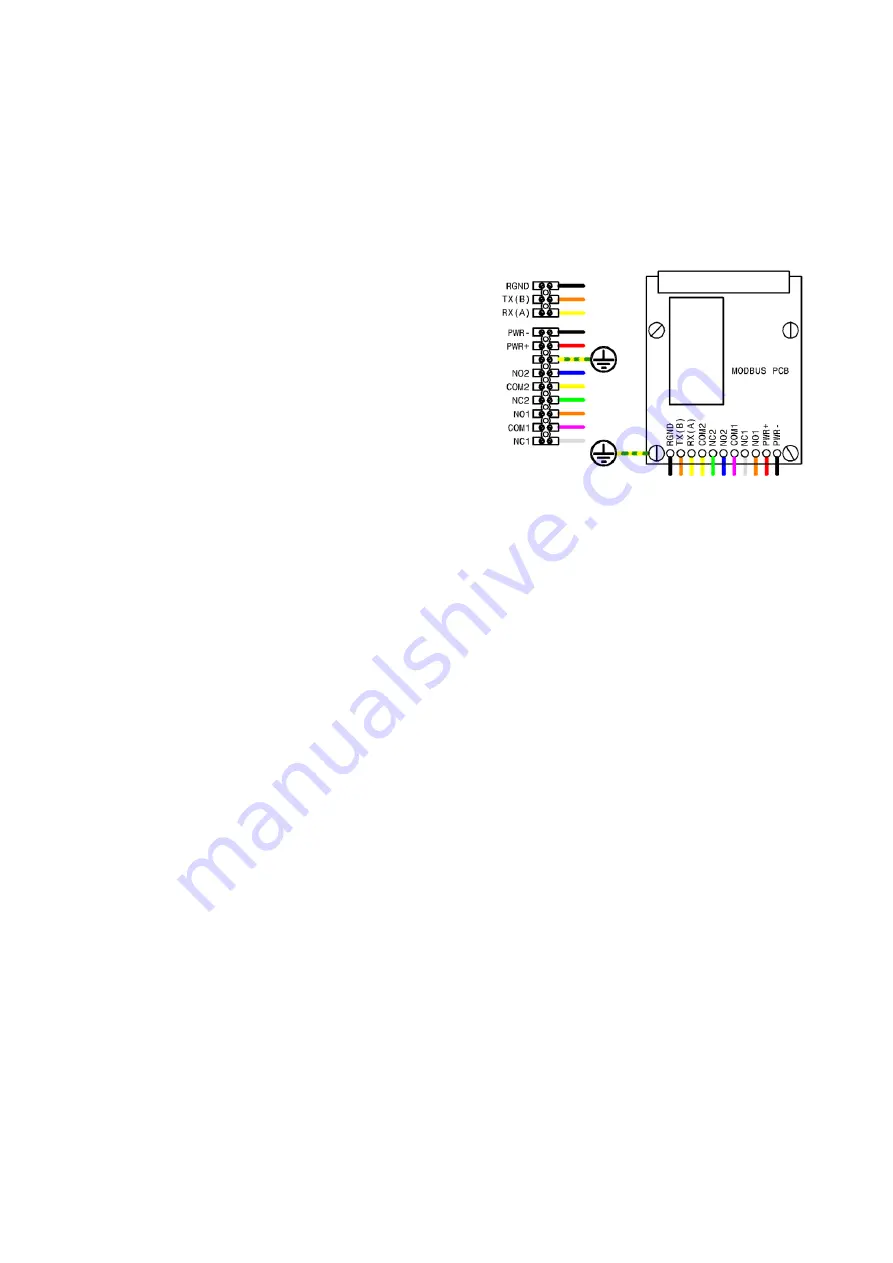
the PCB and are connected to a TERMINAL BLOCK using the wire colours shown below. 
 
RGND  - RS485 ground connection 
TX(B)  - RS485 B connection 
RX(A)  - RS485 A connection 
COM2  - Common contact for relay 2 
NC2  - Normally Closed contact for relay 2 
NO2  - Normally Open contact for relay 2 
COM1  - Positive side of current loop 24VDC supply 
NC1  - Negative side of current loop 24VDC supply 
NO1  - Do not use this connection  
PWR+  - Positive side of external 24VDC supply 
PWR-  - Negative side of external 24VDC supply 
 
Refer to sections 3.5 RELAY OUTPUT and 3.6 CURRENT LOOP OUTPUT. All power supplies must 
provide between 23.0VDC and 25.0VDC. A single power supply may be shared for the positive 
side of external supply and the positive side of the current loop supply. 
 
The  MODBUS  PCB  provides  a  current  loop  output  utilising  connections  COM1  and  NC1  as 
shown above. Because relay 1 is used to control the current loop then inverting the relay logic 
as per section 3.7.7 SET OUTPUT will also reverse the state of the CURRENT LOOP output. 
 
The  only information  provided  over  the  MODBUS  interface  is  the  status  of  the  relay  which  is 
described  in  section  3.5  RELAY  OUTPUT.  Access  to  this  single  ‘bit’  of  information is  accessed 
using MODBUS commands: 


CMD 2 “Read Discrete Input” at coil 8 


CMD 3 “Read Holding Register” at register 0 bit 0. 


CMD 4 “Read Input Register” at register 0 bit 0. 

 
Assuming that the relay logic has not been inverted (see section 3.7.7 SET OUTPUT) then the 
relay bit will be ‘1’ while the relay is in the DETECTION state and ‘0’ while the relay is in the 
LISTENING state. 
 
The  MODBUS  interface  is  configured  by  selecting  SET  OUTPUT->CONFIGURE  MODBUS  in  the 
menu system. There are 3 configurable parameters: 


MODBUS address for the unit (if zero – MODBUS disabled) 


BAUD rate for communications (9600,19200,38400,57600,115200) 


WORD format (no/even/odd parity, 7 or 8 bit word, 1 or 2 stop bits) 

 
If a non-zero address is entered then the MODBUS interface will become active on exit from 
the menu and will await commands. 
 

Summary of Contents for ID5000P

Page 1: ...berdeen AB21 0PS UK 44 0 1224 714 714 www online electronics com sales online electronics com NON INTRUSIVE SIGNALLER ULTRASONIC PASSIVE TOPSIDE OPERATING MANUAL The ID5000P is a fully ATEX certified non intrusive pig signaller which detects signals and logs the passage of pigs at critical points along a pipeline both on land and offshore ...

Page 2: ...5001 Checked IF APPLICABLE Date IF APPLICABLE Approved Date Rev Date By Summary of change A00 07 08 17 BG CR00485 Was ID5000P MANUAL RevB04 CR00380 Address change CR00499 Front cover update A01 14 10 17 BG CR00499 Cover page update COMMENTS ca 12 54 27 12 10 2017 ...

Page 3: ...INGLE BUTTON MENU INTERFACE 9 3 7 1 EXIT 10 3 7 2 STATUS 10 3 7 3 VIEW EVENTS 10 3 7 4 DELETE ALL EVENTS 10 3 7 5 SHUTDOWN 10 3 7 6 MORE 10 3 7 7 SET OUTPUT 11 3 7 8 SET TIME DATE 11 3 7 9 LIVE DISPLAY ON OFF 12 3 7 10 SET FILTERS 12 3 7 11 SET LIMITS 12 3 7 12 SET COEFFICIENTS 12 3 7 13 FACTORY RESET 12 4 RECOMMENDED MAINTENANCE 13 4 1 MAIN BATTERY REPLACEMENT 13 5 EXTERNAL CONNECTIONS 14 5 1 STA...

Page 4: ...everal optional outputs The unit logs the time and date of up to 100 events which can be viewed at any point using the local display The user can turn the unit ON and OFF as well as modify several settings using a single control button and intuitive menu system The unit has two basic parts as shown below The transducer is permanently connected to the main housing via a cable The transducer is scre...

Page 5: ...Housing Ambient Temperature Range NiMH Rechargeable Batteries 20 C to 65 C Transducer Ambient Temperature Range 40 C to 85 C Maximum Pipeline Surface Temperature 150 C ATEX Code II 2 G Ex d ib IIC T5 T6 EC Type Examination Certificate Number TRL08ATEX21161X Housing Material SS Unit Only 316L Stainless Steel Housing Material Al Unit Only Copper Free Aluminium Alloy LM25 Al Transducer Material 316L ...

Page 6: ...ired connect the earth stud on top of the housing to a suitable earth bonding point at the point of installation 3 1 2 TRANSDUCER INSTALLATION 1 For optimum results ensure that the pipeline surface at the point of installation is uniform clean and smooth If the surface is irregular corroded or has flaking paint then an abrasive paper or wire brush should be used to prepare the surface The unit wil...

Page 7: ...ressed the next screen will appear The next screen shows the time and date currently set in the unit This can be changed if required See Section 3 7 8 SET TIME DATE for more information The next screen is the STATUS screen This screen shows the current configuration of several settings See section 3 7 2 STATUS for more information The unit now enters STABILISATION During STABILISATION the unit wil...

Page 8: ...in the DETECTION state The time and date of the pig passage are stored in internal memory and can be viewed later using the menu interface The length of time the unit will remain in this state for is determined by the OUTPUT DELAY value See section 3 7 7 SET OUTPUT for a description of this parameter and how to alter its value It should be configured to give the pig enough time to get out of the r...

Page 9: ...which are discussed in this section While in the menu system every time the user presses the control button the CURSOR will move down one line and the COUNTDOWN INDICATOR will be reset to 5 Once the CURSOR is pointing at the desired item the user simply allows the COUNTDOWN INDICATOR to reach 0 and the selected item will be executed This simple behaviour is used throughout the menu interface to mo...

Page 10: ...played after which the unit will return to LISTENING MODE If the control button is pressed at any point then the unit will immediately return to LISTENING MODE 3 7 4 DELETE ALL EVENTS When DELETE ALL EVENTS is selected a screen showing the message WARNING PRESS TO ERASE ALL EVENTS will appear If the user wishes to delete all logged data then they should press the control button once before the cou...

Page 11: ...tered for the hours HH the unit will latch in DETECTION MODE if a pig is detected and will require the user to press the control button to reset the unit back to LISTENING MODE RELAY LOGIC RELAY NORMAL indicates that the relay outputs will behave as described in Section 3 5 RELAY OUTPUT RELAY INVERTED indicates that the behaviour of the relay outputs will be inverted 3 7 8 SET TIME DATE Selecting ...

Page 12: ...editable items when selected 3 R or S Toggles LIVE DISPLAY between showing raw R or processed data S when selected 4 Z Sets the horizontal zoom level when modified Default value is Z01 5 G Sets the gain when modified Default value is G20 6 x Sets the vertical zoom level when modified Default value is 15x 3 7 10 SET FILTERS These parameters should only be modified by qualified personnel that have b...

Page 13: ... must be in accordance with the manufacturers specifications Failure to use such components may invalidate the certification approval and may make the equipment dangerous 4 1 MAIN BATTERY REPLACEMENT 1 The Special Conditions for Safe Use detailed in section 8 ATEX APPENDIX of this manual must be observed and followed at all times 2 Referring to the figure below use a 3mm AF Hex key to loosen the l...

Page 14: ... and PARTITION PLATE will always already be fitted if a MODBUS or HEATER PCB is fitted at the TERMINAL PCB position If a TERMINAL BLOCK and PARTITION PLATE are not fitted then follow the instructions below to fit them 1 Observe how the wires connected to the transducer cable are routed inside the housing before removing the 2x M4x25 cap screws holding the plastic battery compartment in place and c...

Page 15: ...f external supply and the positive side of the current loop supply 5 2 HEATER PCB OPTION The HEATER PCB is fitted when low temperature operation is required 40 C to 20 C It also provides connections for external power and relay output There is no provision for a current loop output The HEATER PCB should only be used with an EXTERNAL POWER SUPPLY Use with a battery pack is not recommended All conne...

Page 16: ...may be shared for the positive side of external supply and the positive side of the current loop supply The MODBUS PCB provides a current loop output utilising connections COM1 and NC1 as shown above Because relay 1 is used to control the current loop then inverting the relay logic as per section 3 7 7 SET OUTPUT will also reverse the state of the CURRENT LOOP output The only information provided ...

Page 17: ...onsibilities In the UK OEL has joined a registered compliance scheme WeeeCare registration number WEE MP3538PZ SCH Electrical and electronic equipment should never be disposed of with general waste but must be separately collected for the proper treatment and recovery The crossed out bin symbol placed on the product reminds you of the need to dispose of it correctly at the end of its life When buy...

Page 18: ...table cable using a suitable ATEX Certified cable gland 5 Unused cable entries shall be sealed using suitable ATEX certified blanking elements 6 The temperature at the cable entry point may exceed 70 C Cables suitable for use at this temperature must be used 7 Only ID5000 battery packs shall be used with the ID5000P 8 The battery pack must be removed if the external power supply is attached 9 Do n...

Reviews: