


15
START
Subwoofer YES / NO
FRONT Speaker LARGE / SMALL
FRONT Speaker Distance
1 ~9m, 0.3 ~ 30ft
Center Speaker Distance
1 ~9m, 0.3 ~ 30ft
Surround Speaker Distance
1 ~9m, 0.3 ~ 30ft
QUIT
LFE Level Attenuator
0 / –10dB
Center Speaker YES / NO
Surround Speaker YES / NO
PARAMETER SELECTOR
PARAMETER SELECTOR
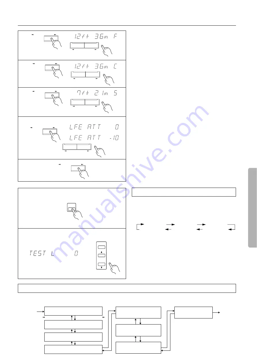
Speaker setup
6. Press the PARAMETER SELECTOR
®
button to display the
front speaker position parameter, and press the PARAME-
TER CONTROLLER
√
/
®
button repeatedly to set the dis-
tance value from your listening position to the front speaker.
Pressing the PARAMETER CONTROLLER
®
button repeatedly
increases the value.
Pressing the
√
PARAMETER CONTROLLER button repeatedly
decreases the value.
Set the value closest to the actual distance.
7. Press the PARAMETER SELECTOR
®
button and use the
PARAMETER CONTROLLER
√
/
®
buttons to set the
center speaker position parameter.
You cannot set the following values:
•
Values larger than the front speaker position setting
•
Values smaller than the value obtained by subtracting “5ft”
from the front speaker setting
8. Press the PARAMETER SELECTOR
®
button and use the
PARAMETER CONTROLLER
√
/
®
buttons to set the sur-
round speaker position parameter.
You cannot set the following values:
•
Values larger than the front speaker position setting
•
Values smaller than the value obtained by subtracting “15ft”
from the front speaker setting
9. Press the PARAMETER SELECTOR
®
button to display
the LFE LEVEL ATT parameter.
10.Press the PARAMETER CONTROLLER
√
/
®
buttons to
select 0 or –10dB.
In general, leave this parameter set to 0dB.
When Dolby digital sound is played and if the bass range is too
loud, set this parameter to “–10dB” to decrease the Low Fre-
quency Effect in the low frequency channel by 10dB.
11.Press the PARAMETER SELECTOR
®
button to return to
the original display.
Use the remote controller and produce the test tone to adjust the
level of the connected speakers.
1. Press the TEST TONE button.
Each speaker produces the test tone (pink noise) in the follow-
ing order:
2. To adjust the level of each speaker, press the CH SEL button
to select a speaker and press the LEVEL
π
/
†
buttons to
raise or lower the level.
The test tone should sound at the same level when you hear it in
your listening position. You can adjust the level in the range
between –12dB and +12dB.
If you adjust the level to +1dB or higher, the overall volume
level will not reach the maximum level when you set the MAS-
TER VOLUME control to its maximum. Refer to the Note on
page 16 for more information.
3. Press the TEST TONE button to complete adjustment.
Test Tone (Remote controller only)
L (Front L ch)
LS (L-Surround)
C (Center ch)
R (Front R ch)
RS (R-Surround)
SW (Subwoofer)
This chart shows how the display changes when the PARAMETER SELECTOR buttons are pressed. Selecting a parameter and pressing the
PARAMETER CONTROLLER button will change the value or setting for the selected parameter.
Parameter selector
dB
dB
or
PARAMETER CONTROLLER
PARAMETER SELECTOR
PARAMETER CONTROLLER
PARAMETER SELECTOR
6
7
8
9, 10
PARAMETER CONTROLLER
PARAMETER SELECTOR
PARAMETER CONTROLLER
PARAMETER SELECTOR
PARAMETER CONTROLLER
PARAMETER SELECTOR
11
dB
LEVEL
CH SEL
1, 3
2
TEST
TONE


