background image


18


Connecting Antenna


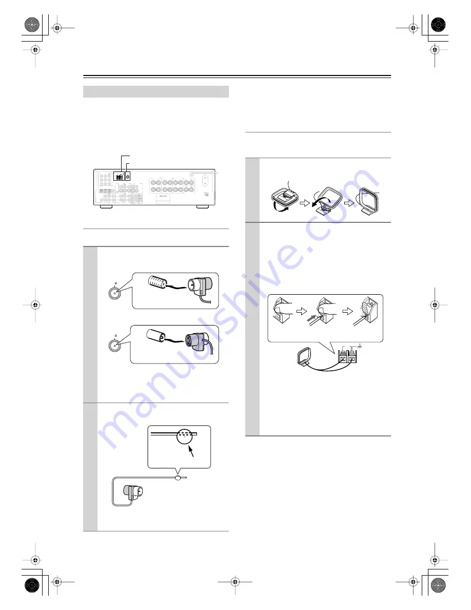
This chapter explains how to connect the supplied indoor 
FM antenna and AM loop antenna and how to connect 
commercially available outdoor FM and AM antennas.
The AV Receiver won’t pick up any radio signals with-
out any antenna connected, so you must connect the 
antenna to use the tuner.


Connecting the Indoor FM Antenna


The supplied indoor FM antenna is for indoor use only.

If you cannot achieve good reception with the supplied 
indoor FM antenna, try a commercially available out-
door FM antenna instead (see page 19).


Connecting the AM Loop Antenna


The supplied indoor AM loop antenna is for indoor use 
only.

If you cannot achieve good reception with the supplied 
indoor AM loop antenna, try using it with a commer-
cially available outdoor AM antenna (see page 19).


Connecting Antenna


1


Attach the FM antenna, as shown.


American Model


Other Models


Once the AV Receiver is ready for use, you’ll need 
to tune into an FM radio station and adjust the 
position of the FM antenna to achieve the best 
possible reception.


2


Use thumbtacks or something similar to 
fix the FM antenna into position.


Caution: 


Be careful that you don’t injure yourself 

when using thumbtacks.

L

R

ANTENNA

FM
75

AM

120 V

VOLTAGE

SELECTOR

220-230 V

SWITCHED
100W MAX.

AC OUTLET

OPTICAL

COAXIAL

1

2

3

DIGITAL IN

VIDEO 1

/ 2 / 3IN

R

L

SURROUND

SPEAKERS

CENTER

SPEAKER

SURROUND BACK

SPEAKER

REMOTE 
CONTROL

IN

IN

IN

IN

IN

IN

IN

FRONT

SURR

CENTER

SUB

WOOFER

OUT

OUT

OUT

VIDEO 2

VIDEO 1

DVD

MONITOR

OUT     

VIDEO

S VIDEO

DVD

TAPE

CD

L

R

VIDEO 2

VIDEO 1

SUBWOOFER

PRE OUT

DVD IN

COMPONENT VIDEO

Y

PB

PR

OUT

L

R

R

L

FRONT

SPEAKERS A

R

L

FRONT

SPEAKERS B

Class 2 Wiring

AM antenna push terminals
FM antenna socket

FM

75

Insert the plug fully 
into the socket.

FM

75

Insert the plug fully 
into the socket.

Thumbtacks, etc.


1


Assemble the AM loop antenna, inserting 
the tabs into the base, as shown.


2


Connect both wires of the AM loop 
antenna to the AM push terminals, as 
shown.


(The antenna’s wires are not polarity sensitive, so 
they can be connected either way around.)
Make sure that the wires are attached securely and 
that the push terminals are gripping the bare 
wires, not the insulation.

Once the AV Receiver is ready for use, you’ll need 
to tune into an AM radio station and adjust the 
position of the AM antenna to achieve the best 
possible reception.
Keep the antenna as far away as possible from the 
AV Receiver, TV, speaker cables, and power 
cords.

AM

Push Insert 

wire

Release

TX-SR502̲En.book Page 18 Friday, March 12, 2004 1:05 PM

Summary of Contents for SR502S - 6.1 Channel Home Theater Receiver

Page 1: ...s in this manual will enable you to obtain optimum performance and listening enjoyment from your new AV Receiver Please retain this manual for future reference Contents Introduction 2 Connection 16 Tu...

Page 2: ...mally by following the operating instructions Adjust only those controls that are covered by the operating instructions as an improper adjustment of other controls may result in damage and will often...

Page 3: ...iver s POWER switch must be set to ON in order to charge the backup system Once it has been charged the AV Receiver will retain the settings for several weeks although this depends on the environment...

Page 4: ...anadian Models NOTE THIS CLASS B DIGITAL APPARATUS COMPLIES WITH CANADIAN ICES 003 For models having a power cord with a polarized plug CAUTION TO PREVENT ELECTRIC SHOCK MATCH WIDE BLADE OF PLUG TO WI...

Page 5: ...0 FM AM presets FM AM auto tuning RDS Radio Data System Europe only Remote Controller Preprogrammed for use with other AV components Table of Contents Important Safety Instructions 2 Precautions 3 Sup...

Page 6: ...this mode E STEREO button 41 This button is used to select the Stereo listening mode American model only F PURE AUDIO button 41 The American model doesn t have this button This button is used to selec...

Page 7: ...is used to access various settings W RETURN button This button is used to return to the previous screen when changing settings X VIDEO 3 INPUT 27 These S Video composite video and analog audio inputs...

Page 8: ...n then be used to control that component To use you must make an analog audio connection RCA between the AV Receiver and the other component even if they are connected digitally Note can only be used...

Page 9: ...uipment that uses infrared rays the remote control ler may not work reliably Don t put anything such as a book on the remote con troller because the buttons may be pressed inadvert ently thereby drain...

Page 10: ...ver To select AMP TUNER mode press the AMP mode button How to Use the Remote Controller 1 Use the REMOTE MODE AMP DVD CD MD CDR TV VCR CABLE SAT buttons to select the modes 2 Uses the buttons supporte...

Page 11: ...n ing mode STEREO button This button is used to select the Stereo listening mode PURE A button not American model This button is used to select the Pure Audio listen ing mode In this mode the display...

Page 12: ...ck buttons From left to right Previous Play Next Fast Reverse Pause Stop and Fast Forward J Step Slow buttons These buttons are used for frame by frame playback and slow motion playback K AUDIO button...

Page 13: ...nkyo CD player con nected to the AV Receiver via To set the remote controller to CD mode press the CD mode button 1 ON button This button is used to set the CD player to On or Standby 2 Number buttons...

Page 14: ...is used to start recording H REPEAT button This button is used to set the repeat playback func tions I OPEN CLOSE button This button is used to eject the MiniDisc or open and close the disc tray of th...

Page 15: ...on is used to set the volume of the AV Receiver 6 MUTING button This button is used to mute the AV Receiver 7 Rewind FF buttons The Rewind button is used to start rewind The FF button is used to start...

Page 16: ...Their role in a home theater is to provide a solid anchor for the sound image They should be positioned facing the listener at about ear level and equidistant from the TV Angle them inward so as to cr...

Page 17: ...All you need to do then is to match the color of each label to the corresponding speaker terminal Connecting the Speaker Cables The following illustration shows which speakers should be connected to...

Page 18: ...yourself when using thumbtacks L R ANTENNA FM 75 AM 120V VOLTAGE SELECTOR 220 230V SWITCHED 100W MAX AC OUTLET OPTICAL COAXIAL 1 2 3 DIGITAL IN VIDEO 1 2 3IN R L SURROUND SPEAKERS CENTER SPEAKER SURRO...

Page 19: ...antenna splitter as shown Connecting an Outdoor AM Antenna If good reception cannot be achieved using the supplied AM loop antenna an outdoorAM antenna can be used in addition to the loop antenna as...

Page 20: ...deo cable Component video separates the luminance Y and color difference signals PR PB providing the best picture quality Some TV manufacturers label their component video sockets slightly differently...

Page 21: ...layer to the S VIDEO DVD IN a video signal will be output by the S VIDEO MONITOR OUT for your TV and the S VIDEO VIDEO 1 OUT for your VCR but not by any composite video or component video outputs Audi...

Page 22: ...L R ANTENNA FM 75 AM OPTICAL COAXIAL 1 2 3 DIGITAL IN REMOTE CONTROL IN IN IN IN IN IN IN IN FRONT SURR CENTER SUB WOOFER OUT OUT OUT VIDEO 2 VIDEO 1 DVD MONITOR OUT VIDEO S VIDEO DVD TAPE CD L R VID...

Page 23: ...and multichannel out puts be sure to use the left and right outputs Connecting a DVD player L R ANTENNA FM 75 AM OPTICAL COAXIAL 1 2 3 DIGITAL IN REMOTE CONTROL IN IN IN IN IN IN IN IN FRONT SURR CENT...

Page 24: ...L R inputs to the analog audio outputs on your VCR as shown L R ANTENNA FM 75 AM OPTICAL COAXIAL 1 2 3 DIGITAL IN REMOTE CONTROL IN IN IN IN IN IN IN IN FRONT SURR CENTER SUB WOOFER OUT OUT OUT VIDEO...

Page 25: ...utputs directly to your recording VCR s AV inputs See the manuals supplied with your TV and VCR for details Video signals connected to composite video inputs can only be recorded via composite video o...

Page 26: ...ing Other Video Sources Satellite Cable Set top box LD Player etc L R ANTENNA FM 75 AM OPTICAL COAXIAL 1 2 3 DIGITAL IN REMOTE CONTROL IN IN IN IN IN IN IN IN FRONT SURR CENTER SUB WOOFER OUT OUT OUT...

Page 27: ...ts to the analog audio outputs on your camcorder games console etc as shown L R ANTENNA FM 75 AM OPTICAL COAXIAL 1 2 3 DIGITAL IN REMOTE CONTROL IN IN IN IN IN IN IN IN FRONT SURR CENTER SUB WOOFER OU...

Page 28: ...you ll need to change the input assignment see page 31 Using Analog Connections Use an analog audio cable to connect the AV Receiver s TAPE IN L R inputs to the recorder s outputs and use another ana...

Page 29: ...onnecting a Turntable L R ANTENNA FM 75 AM OPTICAL COAXIAL 1 2 3 DIGITAL IN REMOTE CONTROL IN IN IN IN IN IN IN IN FRONT SURR CENTER SUB WOOFER OUT OUT OUT VIDEO 2 VIDEO 1 DVD MONITOR OUT VIDEO S VIDE...

Page 30: ...er has AC outlet on its rear panel for con necting the power cord of another AV component The other component s power switch can be left in the ON position so that it turns on or off when the AV Recei...

Page 31: ...he remote controller s AMP button fol lowed by the ON button The AV Receiver comes on the display lights up and the STANDBY indicator goes off To turn off the AV Receiver press the STANDBY ON button T...

Page 32: ...Select if no subwoofer is con nected 4 Use the Down button to select Front and then use the Left and Right buttons to select Small or Large Small Select if the front speakers are small Large Select i...

Page 33: ...Notes If the Surround setting in step 6 is set to None this setting does not appear If the Surround setting in step 6 is set to Small the Large option cannot be selected 8 Press the SETUP button Setup...

Page 34: ...ons Selecting the Source Component 1 Press the AMP button followed by an input selector button to select the component that you want to play The name of the selected source appears on the display as s...

Page 35: ...input are independent of those explained on page 49 Notes While the multichannel input is selected you can select only the Pure Audio or Direct listening mode If you select the multichannel input whil...

Page 36: ...mono Switch back to Auto Tuning mode for stereo Tuning into weak FM stations If the signal from a stereo FM station is weak it may be impossible to get good reception In this case switch to Manual Tun...

Page 37: ...The station is stored and the preset number stops flashing Repeat this procedure for all of your favorite radio stations Selecting Preset Stations 1 Use the TUNER input selector button to select eithe...

Page 38: ...in 2 dB steps Note To bypass the bass and treble tone circuits press the DIRECT or PURE A button to select the Direct or Pure Audio listening mode CD 10 0 CLEAR 1 2 3 4 5 6 7 8 9 V1 V2 V3 DVD MULTI C...

Page 39: ...ug is inserted in the PHONES jack When you connect a pair of headphones the listening mode is set to Stereo unless it s already set to Pure Audio Stereo or Direct When you disconnect the headphones th...

Page 40: ...is NOT set to None page 32 and the Dolby Digital DTS setting page 44 is set to On 4 Available when the Surr Back setting in the Speaker Configuration is NOT set to None page 32 and the Dolby Digital D...

Page 41: ...modes All ST button This button selects the All Ch Stereo listening mode Selecting Listening Modes The Dolby Digital and DTS listening modes can only be selected if your DVD player is connected to th...

Page 42: ...2 channel analog sources It offers six full bandwidth channels with excellent separation There are two modes of oper ation Cinema mode which is suited to movies and Music mode which is for listening...

Page 43: ...o Original DSP Modes Orchestra Suitable for classical or operatic music The center speaker is turned off and the surround channels are emphasized in order to widen the stereo image In addi tion it sim...

Page 44: ...contain a DTS ES flag you can select DTS Dolby EX PL IIx Music or DTS Neo 6 Off DTS 5 1 is used for all DTS sources even if a DTS ES flag is present Dolby Digital DTS setting 5 1 or 6 1 channel playba...

Page 45: ...onnected to theVIDEO 3 INPUTVIDEO socket are recorded by the VCR which is connected to the VIDEO 1 OUT sockets 1 Prepare the camcorder and CD player for playback 2 Prepare the VCR for recording 3 Pres...

Page 46: ...You can set the CinemaFILTER function to On or Off The CinemaFILTER function can be used with the fol lowing listening modes Dolby Digital Dolby Digital EX Dolby Pro Logic II Movie Dolby Pro Logic II...

Page 47: ...he center channel signal output by the center speaker only by the front left and right speakers only phantom center or by a mix of the two 0 to 7 Adjustable range When set to 0 the center channel sign...

Page 48: ...then press the ENTER but ton 3 Use the Down button to select Crossover and then use the Left and Right but tons to select a crossover fre quency Choose a crossover frequency suitable for your setup If...

Page 49: ...t speaker 6 Repeat step 5 for all speakers Note Speakers that you set to No or None in the Speaker Configuration page 32 cannot be selected 7 Press the SETUP button Setup closes Speaker Levels 1 Press...

Page 50: ...utton By default the DVD CD MD CDR mode but tons are preprogrammed with remote control codes for controlling Onkyo components connected via If you ve entered another code for a button and now want to...

Page 51: ...021 4029 4031 Hinari 4017 Hirschmann 4019 4035 Hitachi 4036 4037 Hughes Network Systems 4011 Huth 4013 4015 4024 Imperial 4014 Intertronic 4013 Intervision 4015 4023 4024 Johansson 4015 JVC 4009 4021...

Page 52: ...2037 Firstline 2033 2041 Fisher 2007 2030 2036 Fuji 2004 2010 2024 Funai 2012 Garrard 2012 GE 2001 2002 2008 2010 2011 2023 2025 2026 GEC 2034 GoldHand 2033 GoldStar 2005 2009 Goodmans 2031 2033 Gradi...

Page 53: ...043 1048 1050 1053 1057 Cascade 1035 Celebrity 1002 Century 1040 Cimline 1035 1043 Citizen 1004 1006 1009 1017 1022 1025 Clatronic 1052 Colortyme 1004 1006 Condor 1052 Contec 1035 Contec Cony 1007 100...

Page 54: ...1021 1025 Radiola 1037 Radiomarelli 1040 1067 RCA 1001 1003 1004 1005 1006 1008 1027 1034 Realistic 1010 1017 1034 Rex 1045 1062 RFT 1040 Roadstar 1035 1045 Saba 1040 1062 1066 1069 Saisho 1035 1043 1...

Page 55: ...7 8 9 V1 V2 V3 DVD MULTI CH TAPE TUNER INPUT I ENTER SETUP GUIDE RETURN EXIT TOP MENU MENU VOL CDR SAT AMP _ TV VCR CABLE DVD CD MD DISC CH TONE TUNER TAPE DISPLAY TV INPUT PREV CH DIMMER SLEEP MUTIN...

Page 56: ...s not outputting dig ital audio Check the digital audio output setting on the connected device On some games consoles such as those that support DVD the default setting is off A compatible digital aud...

Page 57: ...ut selector is set incorrectly Select the correct input on the TV i e the input to which the AV Receiver is con nected The video input and output are different for mats The AV Receiver doesn t convert...

Page 58: ...he speakers but it cannot be recorded From the VIDEO 1 OUT you re trying to record the signal being fed into the VIDEO 1 IN or from the TAPE OUT you re trying to record the signal being fed into the T...

Page 59: ...40 dB THD 0 7 Power supply American model AC 120 V 60 Hz Worldwide model AC 220 230 V and 120 V switchable 50 60 Hz Other models AC 230 240 V 50 Hz AC 220 230 V 50 Hz Power consumption American model...

Page 60: ...2600 Fax 201 785 2650 http www onkyousa com ONKYO EUROPE ELECTRONICS GmbH Liegnitzerstrasse 6 82194 Groebenzell GERMANY Tel 49 8142 4401 0 Fax 49 8142 4401 555 http www onkyo net ONKYO CHINA LIMITED U...

Reviews: