background image

Connecting your equipment

2

2

9

2

31

4

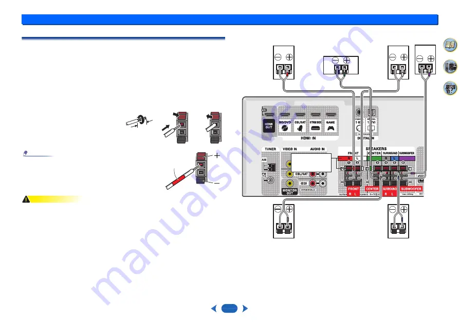
Connecting the speakers

The receiver will work with just two stereo speakers (the front speakers in the diagram) but 
using at least three speakers is recommended, and a complete setup is best for surround 
sound.
Make sure you connect the speaker on the right to the right (

R

) terminal and the speaker on 

the left to the left (

L

) terminal. Also make sure the positive and negative (

+

/

) terminals on the 

receiver match those on the speakers.
You can use speakers with a nominal impedance between 6

Ω

 and 16

Ω

.

Be sure to complete all connections before connecting this unit to the AC power source.

Bare wire connections

CAUTION

These speaker terminals carry 

HAZARDOUS LIVE 

voltage. To prevent the risk of electric 

shock when connecting or disconnecting the speaker cables, disconnect the power cord 
before touching any uninsulated parts.

Make sure that all the bare speaker wire is twisted together and inserted fully into the 
speaker terminal. If any of the bare speaker wire touches the back panel it may cause the 
power to cut off as a safety measure. 

After connecting the plugs, pull lightly on the cables to make sure that the ends of the 
cables are securely connected to the terminals. Poor connections can create noise and 
interruptions in the sound.

If the cables’ wires happen to be pushed out of the terminals, allowing the wires to come 
into contact with each other, it places an excessive additional load on the receiver. This 
may cause the amp to stop functioning, and may even damage the receiver.

When using a set of speakers connected to an receiver, you won’t be able to obtain the 
normal stereo effect if the polarity (+, –) of one of the speakers (left or right) is reversed.

1

Twist exposed wire strands together.

2

Push open the tabs and insert exposed wire.

3

Release the tabs.

Note

Connect the wire with the colored marker to the red (+) 
terminal; the plain wire to the black (–) terminal.

1

2

3

12 mm

(

1

/

2

 in.)

colored 

marker

Center

Surround right

Front right

Front left

Subwoofer

Surround left

Check if the 
colors are the 
same.

Summary of Contents for HT-R397

Page 1: ...Operating Instructions HTP 395 5 1 Channel Home Theater System HT S3900 AV RECEIVER HT R397 Speaker System...

Page 2: ...compatibility 18 Music playback using BLUETOOTH wireless technology 19 Pairing with the unit Initial registration 19 Listen to music on the unit from a BLUETOOTH capable device 19 Radio wave caution 1...

Page 3: ...edure below to make the connections and settings The colors of the steps indicate the following Required setting item Setting to be made as necessary 1 Connecting the speakers Where you place the spea...

Page 4: ...control Cursor buttons TUNING Used to find radio frequencies page 20 PRESET Use to select preset radio stations page 21 These are also used to move the cursors when displaying the Setup for example 8...

Page 5: ...encoded audio signals is detected HD Lights when a source with DTS EXPRESS or DTS HD encoded audio signals is detected 96 24 Lights when a source with DTS 96 24 encoded audio signals is detected NEO...

Page 6: ...ed when the listening mode is set to DIRECT When the front speaker is set at SMALL in the Speaker Setting and the X Over is set above 150 Hz the subwoofer channel level will be adjusted by pressing BA...

Page 7: ...sides of the batteries properly according to the marks in the battery case Batteries with the same shape may have different voltages Do not use different batteries together When disposing of used batt...

Page 8: ...them Putting the speakers on the floor except the subwoofer or mounting them very high on a wall is not recommended For the best stereo effect place the front speakers 2 m to 3 m 6 ft to 9 ft apart a...

Page 9: ...nd inserted fully into the speaker terminal If any of the bare speaker wire touches the back panel it may cause the power to cut off as a safety measure After connecting the plugs pull lightly on the...

Page 10: ...ions Video CD Super VCD and CD This receiver incorporates High Definition Multimedia Interface HDMI technology This receiver supports the functions described below through HDMI connections Digital tra...

Page 11: ...d RCA video cable for coaxial digital connections Standard RCA video cables These cables are the most common type of video connection and are used to connect to the composite video terminals The yello...

Page 12: ...ions on connections and setup for the TV Important When the ARC function is ON and the receiver is connected to a compatible TV with an HDMI cable and you switch the input of the TV to composite the i...

Page 13: ...st switch to the BD DVD Blu ray Disc DVD player or CBL SAT set top box then press AUDIO SEL to choose the audio signal O1 OPTICAL1 see Selecting the audio input signal on page 16 You can only connect...

Page 14: ...ce the AM antenna on a flat surface and in a direction giving the best reception 4 Connect the FM wire antenna into the FM antenna socket For best results extend the FM antenna fully and fix to a wall...

Page 15: ...r outlet CAUTION Handle the power cord by the plug Do not pull out the plug by tugging the cord and never touch the power cord when your hands are wet as this could cause a short circuit or electric s...

Page 16: ...nected to this receiver Selecting the audio input signal The audio input signal can be selected for each input source Once it is set the audio input that was selected will be applied whenever you sele...

Page 17: ...truction manual supplied with your DVD player a The HDMI terminals can be used for the TV input by turning ON the ARC function in the HDMI setting page 29 b In order to listen to the audio from the TV...

Page 18: ...th the receiver switched off Select another input source like BD DVD then switch back to USB Use a dedicated AC adapter supplied with the device for USB power For more information on error messages se...

Page 19: ...input 2 A BLUETOOTH connection will be created between the BLUETOOTH capable device and the unit Procedures for connecting to the unit should be performed from the BLUETOOTH capable device Please refe...

Page 20: ...tening to the radio The following steps show you how to tune in to FM and AM radio broadcasts using the automatic search and manual step tuning functions Once you are tuned to a station you can memori...

Page 21: ...r how to do this 2 Press EDIT twice The cursor at the first character position is blinking on the display 3 Input the name you want Choose a name up to eight characters long Use PRESET to select chara...

Page 22: ...ing on your speaker settings Dolby Digital and DTS multichannel sources are downmixed to stereo When the headphones are connected STEREO can only be selected Using the DSP The DSP feature creates a va...

Page 23: ...e picture By adding a bit of delay you can adjust the sound to match the presentation of the video 0 ms to 500 ms 1 step 5 ms Default 0 M OPT Advanced Music Optimizer a Switches on off the effect of A...

Page 24: ...cturer directly g Only available with 2 channel sources in DOLBY PLII MUSIC mode h Only when listening to 2 channel sources in NEO 6 CINEMA and NEO 6 MUSIC mode C WIDTH Center Width g Applicable only...

Page 25: ...the front panel hold ON STANDBY The setting switches between display and hide each time you operate these steps The functions that can be set differ depending on the input signal or speaker settings D...

Page 26: ...Standby Through output or not during standby see The HDMI Setup menu on page 29 Manual speaker setup This receiver allows you to make detailed settings to optimize the surround sound performance You o...

Page 27: ...kers X Over Default setting 200Hz This setting decides the cutoff between bass sounds playing back from the speakers selected as LARGE or the subwoofer and bass sounds playing back from those selected...

Page 28: ...ignal on page 16 1 Select Manual SP Setup from the Setup 2 Select Speaker Distance from the Manual SP Setup menu 3 Adjust the distance of each speaker using You can adjust the distance of each speaker...

Page 29: ...the Standby Through setting is not set to OFF the power consumption during standby will increase 4 Choose the 4k60p Setting setting you want If the TV to be connected using HDMI supports 4K 60p you c...

Page 30: ...n the connected player This unit may not operate properly if the HDMI CONTROL on the player is ON Refer to the relevant device s instruction manual for details If this does not work turn OFF the ARC f...

Page 31: ...16 Make sure the component is connected correctly see Connecting your equipment on page 8 Check the audio output settings of the source component Refer to the instruction manual supplied with the sou...

Page 32: ...is receiver even if it is HDCP compatible In this case connect using the composite video jacks between source and receiver If video images do not appear on your TV try adjusting the resolution Deep Co...

Page 33: ...sturdy floor surface Mounting the subwoofer on a long pile carpet should be avoided since the carpet may touch the driver s diaphram causing distorted sound Please install the subwoofer away from the...

Page 34: ...hat are securely screwed into the wall Resetting the main unit Use this procedure to reset all the receiver s settings to the factory default Use the front panel controls to do this 1 Switch the recei...

Page 35: ...al In Out Section HDMI terminal Type A 19 pin HDMI output type 5 V 55 mA USB terminal USB2 0 Full Speed Type A 5 V 0 5 A Speaker section Subwoofer Cabinet Bass reflex floor type Speaker 16 cm cone typ...

Page 36: ...rks and trade names are those of their respective owners Manufactured under license from Dolby Laboratories Dolby Dolby Audio Pro Logic and the double D symbol are trademarks of Dolby Laboratories For...

Page 37: ...rranty keep intact all the notices that refer to this License and to the absence of any warranty and give any other recipients of the Program a copy of this License along with the Program You may char...

Page 38: ...conditions are different write to the author to ask for permission For software which is copyrighted by the Free Software Foundation write to the Free Software Foundation we sometimes make exceptions...

Page 39: ...8 138 http www fr onkyo com fr For Product Support Team Only 1 800 229 1687 http www us onkyo com 1 10 5 Yokoami Sumida ku Tokyo 130 0015 JAPAN http www onkyo com Hong Kong Unit 1033 10 F Star House N...

Reviews: