


6
6
IN
VIDEO-1
MONITOR
OUT
OUT IN
VIDEO-2
IN
VIDEO-1
IN OUT
PROCESSOR
FRONT SURROUND
OUT IN
VIDEO-2
SUB-
WOOFER
R L
SURROUND
CENTER
REMOTE
CONTROL
SUB WOOFER
PRE OUT
CENTER
R
L
S VIDEO
VIDEO
SPEAKERS
MULTI
CHANNEL INPUT
OUT IN
VIDEO-2
IN
VIDEO-1
MONITOR OUT
CAUTION:
SPEAKER
IMPEDANCE
6 OHMS MIN.
/SPEAKER
1
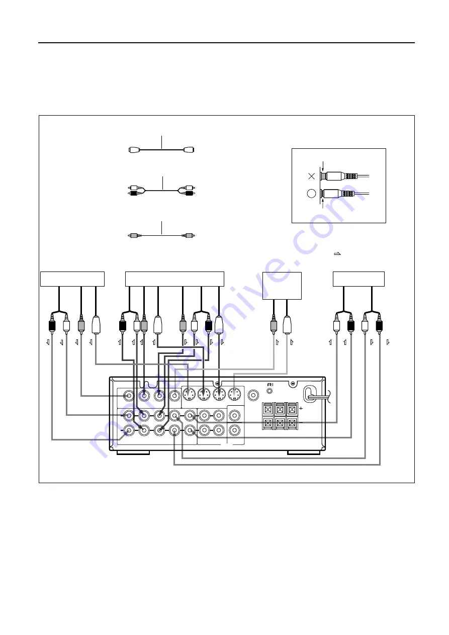
Connecting the amplifier
Connect the amplifier's processor connection jacks to the
ED-205's PROCESSOR IN/OUT jacks.
With an Onkyo amplifier such as A-905 , remove the jumper
plug in the processor jack before connecting the audio
connection cables. The removed jumper plug should be kept
for future use. Never attempt to insert the jumper plug into
any other jacks.
2
Connecting a video disc player or BS tuner
Connect the equipment's Video output jacks to the
ED-205's VIDEO-1 jacks.
Output
Output
Input
Input
(PROCESSOR
IN)
Output
Input
Input
Output
(PROCESSOR
OUT)
Amplifier
(Such as A-905)
Monitor
TV
Video disc player,
BS tuner, etc.
Video cassette recorder
3
Connecting a video cassette recorder
Connect the video cassette recorder's Video jacks to the ED-
205's VIDEO-2 jacks.
4
Connecting a TV monitor
Connect the TV monitor's Video input jack to the
ED-205's Video or S VIDEO MONITOR OUT jack.
Note:
This unit's S VIDEO IN/OUT jacks do not have an S-Video/
Video switching feature. Be sure to connect your video cassette
recorder via either the Video or S-Video connection cable.
Connecting the amplifier and video equipment
• Do not connect the power cord until you complete all other connections.
• Connect the unit to your amplifier via the supplied audio connection cables. Be sure to insert the cable's red plugs into the
Right jacks and white plugs into the Left jacks.
For other connections, use the cables that came with that equipment.
• Insert the plugs and connectors completely. Remember that improper connection results in noise or malfunction.
• Do not bind the audio connection cables with the power cord and speaker cables. Doing so may degrade sound quality.
• The unit’s cover will become hot due to its built-in amplifier. Avoid placing any equipment on the unit.
2
3
4
1
Insert completely
Improper connection
:
Signal flow
Audio connection cable
Video connection cable
S-Video connection cable
S-Video
S-Video
L (left)
R (right)
(Yellow)
V (video)
L
R
V


