background image

PIN NUMBER

DESCRIPTION

PIN NAME

MAIN FUNCTION

TYPE

175

EMI Interface

CPU_ADR[13]

ADR[13]

O

176

EMI Interface

CPU_ADR[14]

ADR[14]

O

177

EMI Interface

CPU_ADR[15]

ADR[15]

O

178

EMI Interface

CPU_ADR[16]

ADR[16]

O

179

EMI Interface

CPU_ADR[17]

ADR[17]

O

180

EMI Interface

CPU_ADR[18]

ADR[18]

O

181

EMI Interface

CPU_ADR[19]

ADR[19]

O

182

EMI Interface

CPU_ADR[20]

ADR[20]

O

183

EMI Interface

CPU_ADR[21]

ADR[21]

O

184

-

VDD3_3

3.3V POWER SUPPLY

POWER

185

-

VSS

GROUND

POWER

186

PIOs and communication

PIO0[0]

PIO0[0]

I/O

187

PIOs and communication

PIO0[1]

PIO0[1]

I/O

188

PIOs and communication

PIO0[2]

PIO0[2]

I/O

189

PIOs and communication

PIO0[3]

PIO0[3]

I/O

190

PIOs and communication

PIO0[4]

PIO0[4]

I/O

191

PIOs and communication

PIO0[5]

PIO0[5]

I/O

192

PIOs and communication

PIO0[6]

PIO0[6]

I/O

193

PIOs and communication

PIO0[7]

PIO0[7]

I/O

194

PIOs and communication

PIO1[0]

PIO1[0]

I/O

195

PIOs and communication

PIO1[1]

PIO1[1]

I/O

196

PIOs and communication

PIO1[2]

PIO1[2]

I/O

197

PIOs and communication

PIO1[3]

PIO1[3]

I/O

198

-

VDD2_5

2.5V POWER SUPPLY

POWER

199

-

VSS

GROUND

POWER

200

PIOs and communication

PIO1[4]

PIO1[4]

I/O

201

PIOs and communication

PIO1[5]

PIO1[5]

I/O

202

PIOs and communication

TRIGGER_IN

TRIGGER_IN FOR DCU

I/O

203

PIOs and communication TRIGGER_OUT

TRIGGER_OUT FOR DCU

I/O

204

PIOs and communication

PIO2[0]

PIO2[0]

I/O

205

PIOs and communication

PIO2[1]

PIO2[1]

I/O

206

PIOs and communication

PIO2[2]

PIO2[2]

I/O

207

PIOs and communication

PIO2[3]

PIO2[3]

I/O

208

PIOs and communication

PIO2[4]

PIO2[4]

I/O

Summary of Contents for DV-S353

Page 1: ...REPLACE THESE COMPONENTS WITH ONKYO PARTS WHOSE PART NUMBERS APPEAR AS SHOWN IN THIS MANUAL MAKE LEAKAGE CURRENT OR RESISTANCE MEASUREMENTS TO DETERMINE THAT EXPOSED PARTS ARE ACCEPTABLY INSULATED FR...

Page 2: ...0 005 Wow and flutter Below measurable level Operating conditions Temperature 5 C to 35 C 41 F to 95 F Operation status Horizontal Outputs Video output 1 0 V p p 75ohm negative sync pin jack 1 S vide...

Page 3: ...INTO BEAM CAUTION THIS PRODUCT UTILIZES A LASER USE OF CONTROLS OR ADJUSTMENTS OR PERFORMANCE OF PROCEDURES OTHER THAN THOSE SPECIFIED HEREIN MAY RESULT IN HAZARDOUS RADIATION EXPOSURE The label on t...

Page 4: ...C b o a r d DisplaycircuitPCboard S1 22 S2 21 S2 24 S1 S1 30 S4 32 33 11 S1 19 23 S1 30 S1 60 CC201 S1 10 S4 34 25 31 S3 S5 S5 S5 31 30 31 31 S1 31 30 S1 S1 S4 S3 50 31 S4 27 S1 S1 35 70 U1 U1 U2 U3 U...

Page 5: ...t Standby ind 30 55125120XX Leg Rear 31 55141370XX Rubber leg 32 J60000005300 Chassis 33 J60100015000 Top cover 34 J60110018000 Rear panel 35 J67200019000 Cover Sensor 50 J85820004000 Shaft power 60 J...

Page 6: ...DV S353 BLOCK DIAGRAM DVD MECHANISM F E MECHA POWER SUPPLY PC BOARD DISPLAY CIRCUIT PC BOARD OUTPUT TERMINAL PC BOARD...

Page 7: ...board Standby LED PC board Search backward Search forward RED Skip backward Skip forward PLAY PAUSE STOP OPEN CLOSE IC901 IC CXP82324 From Power supply PC board Front circuit PC board FL tube FL901 To...

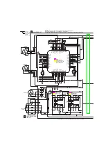
Page 8: ...DV S353 SCHEMATIC DIAGRAM From Main PC board to Pick up M GND Main circuit PC board From Pickup to main PC board From main PC board to front PC board 8V Motor loading VCC 5V Digital VCC...

Page 9: ...DV S353 IC201 ST15519 JIG PCM LRCLK PCM CLK SPDF GND PCM DATAD PCM BICK R OUT G OUT F RESET DXX INTERRUPT IRQ2 To Output terminal PC board To CP801 To CP802...

Page 10: ...DV S353 SCHEMATIC DIAGRAM Output terminal PC board From Main PC board From Main PC board...

Page 11: ...DGND PCM1748E CS PCM1748E CLK PCM1748E DA PCMCLK BCK PCMOUT LRCLK NC NC DGND SPDIF DGND CP803 CN205 RESET MAIN TXD RXD TV AUX CN902 Main circuit PC board Front display PC board NC DGND SECTOR START D...

Page 12: ...4 1kohm Capacitors L210 C901 2026783041 47uF 16V 20 5 x 7 L220B L220G 1404175091 2 7uH Chip C906 2025205041 100uF 6 3V 20 5 x 7 L220R C907 C917 2026862041 470uF 6 3V 20 8 x 9 L501 R415 5512667050 FCM2...

Page 13: ...P202 silkscreened DOWN LOAD on the main Board 5 Turn on the product and make sure the LED on the jig will be light 6 type DVD_DOWN 353v bin then you will see the message below file size 1897904 word s...

Page 14: ...sses are multiplexed on the same pins Row address RA0 RA11 Column address CA0 CA7 BA0 BA1 Bank select address Selects bank to be activated during row address latch time Selects bank for read write dur...

Page 15: ...POWER GND 25 Video DAC B_OUT B_OUT O 26 Video DAC G_OUT G_OUT O 27 Video DAC R_OUT R_OUT O 28 Video DAC V_REF_RGB V_REF_DAC_RGB I 29 Video DAC I_REF_RGB I_REF_DAC_RGB I 30 Video DAC VDD_YCC VDDA_YCC 2...

Page 16: ...memory interface SMI_CLKIN SDRAM CLOCK IN O 83 VSS GROUND POWER 84 Share memory interface SMI_DATA 0 DATA BUS SDRAM I O 85 Share memory interface SMI_DATA 1 DATA BUS SDRAM I O 86 Share memory interfac...

Page 17: ...0 I O 142 EMI Interface CPU_DATA 1 DATA 1 I O 143 EMI Interface CPU_DATA 2 DATA 2 I O 144 EMI Interface CPU_DATA 3 DATA 3 I O 145 EMI Interface CPU_DATA 4 DATA 4 I O 146 EMI Interface CPU_DATA 5 DATA...

Page 18: ...communication PIO0 4 PIO0 4 I O 191 PIOs and communication PIO0 5 PIO0 5 I O 192 PIOs and communication PIO0 6 PIO0 6 I O 193 PIOs and communication PIO0 7 PIO0 7 I O 194 PIOs and communication PIO1 0...

Page 19: ...otice Bank Select Data Input Register 1M x 16 1M x 16 Sense AMP Output Buffer I O Control Column Decoder Latency Burst Length Programming Register Address Register Row Buffer Refresh Counter Row Decod...

Page 20: ...NPN L801 L804 20441240XX Wire buss 7 5mm Q804L 5513319092 DTA114YKA Chip PNP L808 Q803 Q804 5513869056 KTN2907A PNP L803 L810 20441210XX Wire buss 20mm Q807 L811 20441240XX Q808 Q809 5513871092 KTD13...

Page 21: ...EDICATED OUTPUT PORT SEGMENT SIGNAL OUTPUT FOR FDP O 39 PD5 S5 8 BIT DEDICATED OUTPUT PORT SEGMENT SIGNAL OUTPUT FOR FDP O 40 PD6 S6 8 BIT DEDICATED OUTPUT PORT SEGMENT SIGNAL OUTPUT FOR FDP O 41 PD7...

Page 22: ...d L 15 J90300022000 Warrany card 8 J94330001000 3P1500 Audio connection cable J90400048000 POS label 17 55167260XX Remote controller RC 458DV with poly cover 10 J97000501010 Poly bag Power cord 18 301...

Page 23: ...Park Way Upper Saddle River N J 07458 U S A Tel 201 785 2600 Fax 201 785 2650 E mail onkyo onkyousa com Sales Product Planning Div 2 1 Nisshin cho Neyagawa shi OSAKA 572 8540 JAPAN Tel 072 831 8111 F...

Page 24: ...memory interface SMI_CLKIN SDRAM CLOCK IN O 83 VSS GROUND POWER 84 Share memory interface SMI_DATA 0 DATA BUS SDRAM I O 85 Share memory interface SMI_DATA 1 DATA BUS SDRAM I O 86 Share memory interfac...

Page 25: ...0 I O 142 EMI Interface CPU_DATA 1 DATA 1 I O 143 EMI Interface CPU_DATA 2 DATA 2 I O 144 EMI Interface CPU_DATA 3 DATA 3 I O 145 EMI Interface CPU_DATA 4 DATA 4 I O 146 EMI Interface CPU_DATA 5 DATA...

Page 26: ...communication PIO0 4 PIO0 4 I O 191 PIOs and communication PIO0 5 PIO0 5 I O 192 PIOs and communication PIO0 6 PIO0 6 I O 193 PIOs and communication PIO0 7 PIO0 7 I O 194 PIOs and communication PIO1 0...

Reviews: