background image

16

Connecting Speakers

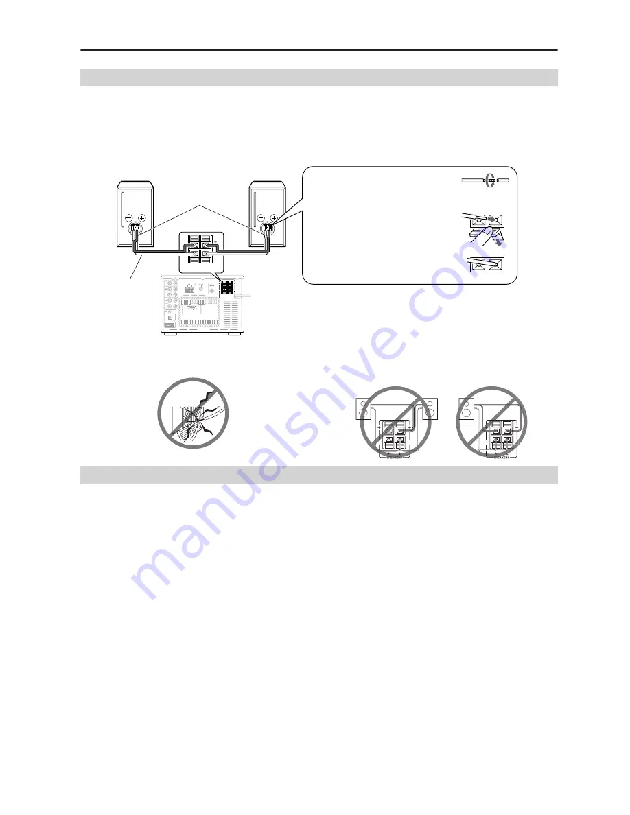
• Connect the right channel speaker to the R speaker connector on the CD receiver, and the left channel speaker to the 

L speaker connector.

• Connect the “+” connector on each speaker to the “+” connectors on the CD receiver, and connect the “–” connector 

on each speaker to the “–” connectors on the CD receiver. Use the red wires of the speaker cables to connect the “+” 
connectors.

• To prevent damage to circuits, never short-circuit the 

positive (+) and negative (–) speaker wires.

• Do not connect the speaker cord to the L and R connec-

tors at the same time (i.e., 1). Do not connect more than 
two speaker connectors to the same speaker (i.e., 2).

The sound quality a speaker system reproduces varies 
greatly depending on room construction and area of the 
room in which it is installed, as well as the location and 
size of the furniture. For better-quality sound, observe 
the following precautions.
• Placing the speaker system directly on the floor can 

result in undesirable boom, that is, sound with 
extremely heavy bass. Place each speaker on a speaker 
stand, concrete blocks, bricks or a rigid bookshelf.

• High-quality bass sound cannot be obtained if the 

speakers are not seated on a stable speaker stand or 
other base.

• To obtain a deeper bass sound, mount the speakers on 

lower speaker stands and place them in front of a wall 
of sufficient rigidity.

• In many rooms, the furniture and walls affect the 

reproduced sound quality. For stereo sound reproduc-
tion, placing the right and left speakers in the same 
relative position produces the best results. If they are 
placed in extremely different positions, the right- and 
left- channel balance will be adversely affected.

• The ideal placement of the speaker system is as fol-

lows: Imagine an equilateral triangle and position the 

right and left speakers on both ends of the base. The 
ideal listening position is at or slightly to the rear of 
the triangle apex.

• Glazed doors or surrounding walls in front of the 

speaker system may resonate specific frequency 
ranges due to reflected sound. To eliminate this reso-
nance, place some sound-absorbing material, such as 
a thick curtain, in front of the doors or walls.

Tips:

• The speaker cabinet is made of wood and is therefore 

sensitive to extreme temperatures and humidity. Avoid 
placing the speakers in locations subject to direct sun-
light, or in smoky or humid places.

• Place the unit on a rigid, level surface.

Connecting the Speakers

SPEAKERS

PRE OUT

R

L

REMOTE

CONTROL

OPTICAL

I N

OUT

I N

I N

OUT

R

L

R

L

DIGITAL OUT

ANTENNA

SPEAKERS

R

L

1. Peel the insulation to expose the 

core wire and twist the core wire.

2. Pull down the lever and insert 

the tip of the speaker cable.

3. Release the lever to affix the 

wire.

• Be sure to connect speakers that have an impedance of 

4 ohms to 16 ohms. Connecting a speaker with an 
impedance lower than 4 ohms may damage the 
speaker.

Red wire

Right channel 
speaker

Left channel 
speaker

Speaker 
cable

i.e., 1

i.e., 2

Placement

Summary of Contents for CR-N7

Page 1: ...connections and plugging it in Following the instructions in this manual will enable you to obtain optimum performance and listening enjoyment from your new CD Receiver Please retain this manual for...

Page 2: ...aratus does not operate normally by following the operating instructions Adjust only those controls that are covered by the operating instructions as an improper adjustment of other controls may resul...

Page 3: ...on is inadequate the unit may overheat leading to malfunction Do not expose this unit to direct sunlight or heat sources because its internal temperature may rise shortening the life of the optical pi...

Page 4: ...he terminal which is marked with the letter N or coloured black The wire which is coloured brown must be connected to the terminal which is marked with the letter L or coloured red IMPORTANT The plug...

Page 5: ...ame room or the CD receiver is installed close to equipment that uses infrared rays the remote con troller may not work reliably Don t put anything such as a book on the remote con troller because the...

Page 6: ...electing a Source 22 Listening through the Headphones 22 Adjusting Bass 23 Emphasizing the Low End Using the Remote Controller 23 Adjusting Treble 23 Muting the Sound 23 Playing a CD 24 Selecting the...

Page 7: ...he 12 hour and 24 hour Displays 46 Turning the Current Time Display On or Off while the Unit is in Standby Mode 46 Using the Timer Functions 47 About the Timers 47 About the Sleep Timer 47 Using the S...

Page 8: ...a group on MP3 discs K DISPLAY button 25 28 39 42 Each time you press this button the information on the display changes This button also enables you to select the input character type L TIMER button...

Page 9: ...CD playback F MP3 indicator This indicator lights up when a MP3 CD is loaded G SLEEP indicator This indicator lights up when the Sleep function has been set H TIMER indicators These indicators show t...

Page 10: ...FER jack is for connecting a pow ered subwoofer G SPEAKERS 16 These terminals are for connecting speakers H REMOTE CONTROL 18 20 This Remote Interactive jack can be con nected to an jack on another On...

Page 11: ...tops playback recording fast forward or rewind Plays the A side J HDD PLAYLIST button When input is HDD skips up or down the play list K TIMER button 44 45 49 Press this button to enable the timer fun...

Page 12: ...a sampling rate of between 8 kHz and 48 kHz and a bit rate of between 8 kbps and 320 kbps 128 kbps recommended Incompatible files cannot be played Constant Bit Rate MP3 files are recommended how ever...

Page 13: ...ain MP3 tracks organized into groups Handling Discs Never touch the underside of a disc Always hold discs by the edge as shown Never attach adhesive tape or sticky labels to discs Cleaning Discs For b...

Page 14: ...M radio station and adjust the position of the FM antenna to achieve the best possible reception 2 Use thumbtacks or something similar to fix the FM antenna into position Caution Be careful that you d...

Page 15: ...st be grounded in accordance with local regulations to prevent electrical shock haz ards Using a TV FM Antenna Splitter It s best not to use the same antenna for both FM and TV reception as this can c...

Page 16: ...e and walls affect the reproduced sound quality For stereo sound reproduc tion placing the right and left speakers in the same relative position produces the best results If they are placed in extreme...

Page 17: ...jacks have shutter type covers that open when an optical plug is inserted and close when it s removed Push plugs in all the way Caution To prevent shutter damage hold the optical plug straight when in...

Page 18: ...using the supplied remote controller You also need to connect the analog audio cable When the connected Onkyo stereo cassette tape deck plays back the input selector on the CD receiver is automati cal...

Page 19: ...When the connected Onkyo RI Dock plays back the input selector on the CD receiver is automatically switched to HDD If the source name assigned to HDD jacks is CD R it should be reset to HDD default se...

Page 20: ...nter the new name You may press YES MODE instead of MULTI JOG to get the same result The jack connection enables you to use the following functions You can control a connected Onkyo compact disc recor...

Page 21: ...The ACCUCLOCK function automatically updates the clock daily at 2 A M 3 A M and 2 P M If the clock has not been set correctly see Setting ACCUCLOCK to Use a Specific Station on page 44 and Setting the...

Page 22: ...lume or counterclockwise to decrease the volume on the unit Press VOLUME on the remote controller You can select CD FM AM or connected external audio video equipment HDD TAPE LINE as the audio source...

Page 23: ...ss 2 Press to adjust and ENTER to set The factory default value is set to 0 you can adjust the value by increment or decrement of 2 steps between 10 and 10 To adjust treble press ENTER Note If you lea...

Page 24: ...the unit always searches the desired point 10 times faster For MP3 discs fast reverse only works within the MP3 track that s currently playing In addition fast forward and fast reverse may not work sm...

Page 25: ...n order press repeatedly For MP3 discs you can also select tracks in other groups Adjust the volume level Press VOLUME to raise the level and VOLUME to lower the level Press to play Playback starts if...

Page 26: ...his mode can only be used while playback is stopped If in Random mode pressYES MODE to switch to Nor mal mode Selecting MP3s Track11 Track1 Track10 Group3 Track12 Root Group1 Group2 Track13 Group4 Tra...

Page 27: ...r starts playback If you have operated the above mentioned control during playback press ENTER 3 Press the number buttons to enter the track number Playback starts automatically If the group contains...

Page 28: ...ng rate and bit rate of the current track Notes To display the disc name while playback is stopped press DISPLAY If a track or group name contains a character that can not be displayed it will be disp...

Page 29: ...r lights in the dis play 2 Turn MULTI JOG to select the first track you want to play back then press MULTI JOG To select the next track to be played repeat this step You can also use the number button...

Page 30: ...ory 1GR MP3 CD only or Random playback mode The 1 Track Repeat mode is available only in combination with normal playback Random Playback 1 Press YES MODE repeatedly until the RDM indicator lights in...

Page 31: ...the unit is stopped Cancels Repeat or 1 Track Repeat mode Cancelling the Playback Mode 1 Press to stop playback 2 Press YES MODE repeatedly until NORMAL indicator lights in the display Press REPEAT r...

Page 32: ...e Not Replace This preference determines whether or not track and group names that contain undisplayable characters are replaced with TRACK n or GROUP n n being the track or group number When set to N...

Page 33: ...omitted when the track or group name appears on the display If you have created MP3 CD on PC you can not specify the order of the playback files However by assigning a series of numbers such as 01 02...

Page 34: ...f the preset FM stations and one of the preset AM stations could use the same channel number The Preset Write function enables you to store radio station frequencies to any channel num ber For example...

Page 35: ...ge 42 Erasing a preset channel see page 41 Copying the radio station in the selected channel to another see page 40 If Overwrite appears The channel you ve selected is registered already To register t...

Page 36: ...channel see page 42 Erasing a preset channel see page 41 Copying the radio station in the selected channel to another see page 40 Programming FM Stations Automatically Auto Preset 1 2 2 4 If any radio...

Page 37: ...umber or turn it clock wise to select a higher channel number 1 2 Display AUTO SOURCE FM ST AUTO SOURCE FM ST 2 1 Using the remote controller Adjusting the Antenna 1 2 Change the direction of the ante...

Page 38: ...If reception is poor or much noise is heard press YES MODE to turn off the AUTO indicator and switch to monaural reception In this way you can reduce noise or dropped signals To return to AUTO tuning...

Page 39: ...choose a station broadcasting your favorite categories of music or other information The information of Program Service Name and Radio Text is available for display on the CD receiver The RDS indicat...

Page 40: ...so copied to the other channel Tips for Changing the Preset Channels Copying a Preset Channel Preset Copy 1 Call the preset channel you wish to copy 2 Press EDIT NO CLEAR and turn MULTI JOG until Pres...

Page 41: ...2 Press EDIT NO CLEAR and turn MULTI JOG until PresetErase appears in the display 3 Press MULTI JOG A message requesting confirmation appears in the display To stop erasing press EDIT NO CLEAR 4 Pres...

Page 42: ...omplete the operation execute Step 5 Naming a Preset Channel Entering a Name 1 Press EDIT NO CLEAR and turn MULTI JOG until Name In appears in the display 2 Press MULTI JOG 3 Press DISPLAY repeatedly...

Page 43: ...rom the Remote Controller 2 3 1 3 3 4 1 Press EDIT NO CLEAR 2 Press ENTER 3 Press DISPLAY repeatedly until the character type you wish to enter appears in the display Each press of the DISPLAY button...

Page 44: ...ccuClock or AccuClock appears on the display If Manual Adjust appears turn MULTI JOG to select AccuClock or AccuClock 3 Press MULTI JOG The display appears as shown 4 Use to tune into the FM station T...

Page 45: ...e setting You can now set the time EDIT NO CLEAR STANDBY ON 2 8 1 Display DISPLAY button SUN Sunday MON Monday TUE Tuesday WED Wednesday THU Thursday FRI Friday SAT Saturday 7 Turn MULTI JOG to set th...

Page 46: ...on the display First turn on the power to the unit then press and hold down the STANDBY ON button on the unit for more than two seconds Displaying the current time in Standby mode consumes more power...

Page 47: ...orning Timer Play Every Everyday 7 00 7 30 Timer 2 Records a radio program every week Timer Rec Every MON SAT 15 10 15 30 Timer 3 Records a radio program only this Sunday Timer Rec Once SUN 10 00 12 0...

Page 48: ...er The Sleep timer can be set for 10 to 90 minutes in inter vals of 10 minutes SLEEP 1 Press and hold TIMER for more than one second Sleep 90 appears in the display win dow The unit will turn off in 9...

Page 49: ...TIMER to select the desired timer number Select from Timer 1 to 4 then press MULTI JOG If only Clock is displayed the day of the week and time have not been set Set the day of the week and time 2 Turn...

Page 50: ...the timer operates on the specified day s of every week Turn MULTI JOG to select the day s of the week When the desired day of the week is displayed press MULTI JOG Days Set You can specify the range...

Page 51: ...ace the unit in Standby mode Notes Even if you set Memory Random or 1GR mode for timer playback the CD receiver will perform normal playback at the timer On time If the unit is not in Standby mode the...

Page 52: ...g timer has been programmed 2 Turn MULTI JOG to switch the timer on or off After the timer is switched on or off the unit displays the previous screen 2 1 Display 1 or Viewing the Timer Settings 1 Rep...

Page 53: ...sound Disconnect the headphones See page 22 Sound is not good Make sure that the speaker cords are connected correctly Check their polarity See page 16 Connect the analog audio cables firmly See page...

Page 54: ...rammed preset channels are lost program them again The clock data is lost Set the clock and timers again Radio frequency is not adjustable Press to adjust radio frequency The RDS function does not wor...

Page 55: ...uring timer operation the current timer setting is cancelled The timer operation uses the volume level that was set before the unit was placed in Standby mode Set an appropriate volume level before yo...

Page 56: ...wer Consumption 0 3 W Dimensions W x H x D 205 W x 147 H x 356 D mm Weight 4 3 kg Analog Inputs LINE TAPE HDD Digital Outputs Optical 1 Analog Outputs TAPE HDD Subwoofer Pre Outputs 1 Speaker Outputs...

Reviews: