background image

33

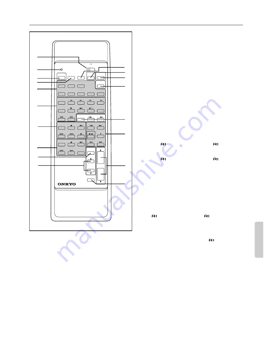
Remote controller RC-374M

A

A/B/LEARN selector switch
(A/B-SUB ROOM/LEARN) [26, 27, 29]

This switch features three functions as follows:
A — Set the switch to this position when you are using the
remote controller in the main room. All buttons on the remote
controller can be used. (The PROGRAMMABLE AREA TV/
VIDEO buttons are used to store remote controller functions for
TV and Video equipment.)
B-SUB ROOM — Set the switch to this position when you are
using the remote controller in the sub room.
LEARN — Set the switch to this position when you are regis-
tering functions of another remote controller.

B

Sending/learned indicator [26, 27]

C

Power button (POWER) [13]

D

Sleep button (SLEEP) [19]

E

Input selector buttons [16]

(Video-1, 2, DVD, PHONO, CD, TUNER, TAPE-1, TAPE-2)

F

PROGRAMMABLE AREA TV/VIDEO buttons [26, 27]

Use these buttons to store remote controller functions of TV and
video equipment. For details, please refer to “Programming
remote controller codes” on pages 26-27.

G

CD operation buttons

These buttons are used to operate an ONKYO CD player that
bears the 

 terminal. (Refer to page 7 for 

 connection.)

H

DVD operation buttons

These buttons are used to operate an Onkyo DVD player that
bears the 

 terminal. (Refer to page 7 for 

 connection.)

I

Channel selector button (CH. SEL) [15, 23]

J

Level 

π

/

 buttons (LEVEL 

π

/

) [15, 23]

K

DIMMER button (DIMMER) [18]

This button can be used to change the brightness of the display.
The brightness changes in three steps: bright, medium, dim.

L

Test tone button (TEST) [15]

M

Surround mode button (SURROUND MODE) [20]

N

Multi channel input button [16, 23]

O

Tuner operation buttons

These buttons are used to operate an ONKYO tuner that bears
the 

 terminal. (Refer to page 7 for 

 connection.)

GROUP: — Group selector button
PRESET 

/

®

: — Preset memory down/up buttons

P

Tape operation buttons

These buttons control ONKYO cassette tape decks that can be
remotely controlled. (Refer to page 7 for 

 connection.)

Q

Volume buttons (VOLUME 

π

/

) [16, 18, 29]

To adjust the volume of the Front Main, Center, or Rear (Sur-
round) speakers, set the A/B-SUB ROOM/LEARN switch to A,
and use these buttons.
To adjust the level of the Remote speakers (perhaps in another
room), set the A/B-SUB ROOM/LEARN switch to B-SUB
ROOM, and use these buttons.

R

Audio muting button (MUTING) [19]

(When the A/B/LEARN selector switch 

1

 is set to A)

REMOTE SPEAKER button (REMOTE SPEAKER) [29]

(When the A/B/LEARN selector switch 

1

 is set to B)

G

H

O

P

A

B

C
D
E

F

K
L
M

N

R

Q

I

J

POWER

SLEEP

DVD

VIDEO-1

VIDEO-2

TAPE-1

TUNER

PHONO

C D

SOURCE SELECTOR

DVD

SUBTITLE

ON/OFF

PAUSE

/STEP

DISC

GROUP

VOLUME

TAPE

DIMMER

TAPE-2

POWER

POWER

VOLUME

C H

TV/VCR

MUTING

/REMOTE

SPEAKER

LEVEL

REMOTE CONTROLLER

CH SEL

TEST

TONE

SENDING/

LEARNED

LEARN

SUBROOM

PRESET

A B

PROGRAMMABLE AREA  TV/VIDEO

TUNER

CD

MULTI-CH

INPUT

RC-374M

SUR

MODE


Summary of Contents for A-DS650

Page 1: ...GITAL AUDIO SELECTOR SMART SCAN CONTROLLER ENTER SURROUND PARAMETER 3 D BASS MAIN REMOTE SPEAKERS REC OUT MULTI SOURCE Re EQ MIDNIGHT THEATER C D PHONO TUNER TAPE 2 MONITOR TAPE 1 M D VIDEO 2 VCR 2 TV VIDEO 1 VCR 1 DVD INPUT SELECTOR MULTI CH INPUT MASTER VOLUME TREBLE BASS AUDIO VIDEO CONTROL AMPLIFIER A DS650 MAX MIN SYSTEM POWER ON PHONES STAND BY OFF MULTIPLE SOURCE REMOTE SYSTEM HIGH DEFINITI...

Page 2: ...to the outlet try reversing it If there is still trouble the user should seek the services of a qualified electrician Under no circumstances should the user attempt to defeat the polar ization of the plug 12 Power Cord Protection Power supply cords should be routed so that they are not likely to be walked on or pinched by items placed upon or against them especially near plugs con venience recepta...

Page 3: ...in any doubt please consult a qualified electrician For U S model Note to CATV system installer This reminder is provided to call the CATV system installer s attention to Section 820 40 of the NEC which provides guidelines for proper grounding and in particular specifies that the cable ground shall be connected to the grounding system of the building as close to the point of cable entry as practic...

Page 4: ...tire system and delivering surround sound whenever TV is turned on audio triggered General Features MULTIROOM MULTISOURCE CAPABILITY with Main Remote speaker selector and outputs to play two different sources simultaneously without the need of an additional ampli fier LARGE 35 SEGMENT DOT MATRIX FLUORESCENT DIS PLAY for more refined natural looking numbers and letters that are easier to read and t...

Page 5: ...age but with the increased channel separation it gives a far greater sense of movement and sound localization Just like in the theater the addition of the active center channel ensures that all audience members hear dialogue coming from its on screen sources regardless of seating position HALL Surround This mode is especially suitable for media that already has a sub stantial amount of reverb soun...

Page 6: ...x months depending on the frequency of use Use spare batteries of the type specified in the table below We recommend that long life AA LR6 or AM 3 size alkaline batteries be used The STAND BY indicator lights up when the unit receives a signal from the remote controller The following information will help you get optimal use from the remote controller Place this amplifier away from direct bright l...

Page 7: ...on can result noise poor performance or damage to the equipment DIGITAL AUDIO SELECTOR SMART SCAN CONTROLLER ENTER SURROUND PARAMETER 3 D BASS MAIN REMOTE SPEAKERS REC OUT MULTI SOURCE Re EQ MIDNIGHT THEATER C D PHONO TUNER TAPE 2 MONITOR TAPE 1 M D VIDEO 2 VCR 2 TV VIDEO 1 VCR 1 DVD INPUT SELECTOR MULTI CH INPUT MASTER VOLUME TREBLE BASS AUDIO VIDEO CONTROL AMPLIFIER A DS650 MAX MIN SYSTEM POWER ...

Page 8: ...he A DS650 amplifier has a powerful digital signal processor for use with DVD players DAT decks and CD players The digital inputs DIGITAL 1 DIGITAL 2 and DIGITAL 3 can be assigned to individual input selector buttons so when an input selector but ton is pressed the assigned digital input is used instead of the corresponding analog input See page 17 A DVD or other component equipped with a digital ...

Page 9: ...V Monitor TV VIDEO IN Video Cassette Recorder VIDEO 1 Video Cassette Recorder VIDEO 2 AUDIO IN VIDEO IN AUDIO OUT AUDIO OUT VIDEO OUT VIDEO OUT AUDIO IN VIDEO IN On each pair of connectors the connector marked R red corresponds to the right channel and the connector marked L white to the left channel The yellow connector marked V is used for video connection Please refer to the instruction manual ...

Page 10: ...EO 2 Provided that the input selector is set to VIDEO 2 the amplifier will be automatically switched off five minutes after the TV is turned off If a mono TV is used connect the audio output of the TV to the VIDEO 2 IN L connector When you power off the TV flashes on the left side of the A DS650 s display and five minutes later the A DS650 also turns off When the IPM system is set to ON the video ...

Page 11: ... 1 meter 3 feet above the listener s ear level and toward the sides of the room making sure that the listener is within the speakers dispersion angle These speakers produce the feel of a moving sound while creating the sensation of being in the middle of the action Subwoofer Install a subwoofer with a built in power ampli fier for powerful bass sounds The placement of the sub woofer does not affec...

Page 12: ...ONTROL R SURROUND CENTER SUBWOOFER DIGITAL 3 COAXIAL MULTI CHANNEL INPUT L R L R L FRONT SPEAKERS MAIN CENTER SPEAKER SURROUND SPEAKERS FRONT REMOTE SPEAKERS L R R L Front Main Speakers L R R Surround Speakers L AC OUTLETS SWITCHED TOTAL 100W MAX 50Hz AC230V Active subwoofer Subwoofer Speaker Amplifier CAUTION SPEAKER IMPEDANCE 6 OHMS MIN SPEAKER V OUT IN OUT IN IN FRONT DIGITAL INPUT DIGITAL 1 OP...

Page 13: ... on off the power to both the A DS650 and the connected audio devices Note If your A DS650 has a POWER switch first turn it on The shape number and total capacity of the AC outlets may differ depending on the area of purchase Make sure that the total capacity of other components connected to this unit does not exceed the capacity that is printed on the rear panel ON OFF SYSTEM button POWER switch ...

Page 14: ...ired option You cannot select Surround LRG if you have selected Front SML in step 6 If the surround speaker parameter is set to Surround NON you may select STEREO or DOLBY 3 stereo as Surround mode To use Surround mode you should at least select either the center or surround speakers Other wise Surround mode is disabled and the unit remains in STEREO mode Speaker Settings LRG Large Select this for...

Page 15: ...t tone will not sound 13 2 Rotate the SMART SCAN CONTROLLER to set the level 30 dB to 12 dB for subwoofer 12 dB to 12 dB for others while the name of the speaker you wish to adjust appears on the display Repeat step 13 2 to adjust all speaker levels until the test signal level sounds the same from all speakers You can also use the remote controller for this step press the CH SEL button to select a...

Page 16: ... Surround mode refer to pages 20 to 23 Press the MULTI CH INPUT button if you wish to listen to a multi channel source connected to the MULTI CHANNEL INPUT Note that the MULTI CH INPUT button does not affect the video source selection See page 23 for more information on MULTI CH INPUT 3 Start playing the selected input source Follow the operating instructions for the source unit 4 Adjust the volum...

Page 17: ...input selector button then press the DIGITAL AUDIO SELECTOR button Turn the SMART SCAN CONTROL LER to select ANALOG then press the ENTER button Even when the digital inputs are used the analog connect ing cables must be left in place Otherwise the multi room remote system TAPE OUT and REC OUTs will not work See page 8 When a Dolby Digital source is played for example appears on the display indicat...

Page 18: ...e REMOTE indicator lights up Turn on these speakers when using multiple sources See page 29 The MASTER VOLUME control knob adjusts the volume of the front center surround and subwoofer speakers simulta neously Turning it clockwise increases the volume You can also adjust the volume using the remote controller s VOL UME π buttons The Master Volume level settings are dB minimum 58 1 0 1 18dB maximum...

Page 19: ...eep timer is operating the SLEEP indicator is lit If you press the sleep button during this time the amount of time remaining on the timer is displayed and if you press the button during that display 10 minutes will be subtracted from that time If you press the button when the panel display indicates 10 minutes or less the sleep timer will be cancelled and the power will not be turned off This but...

Page 20: ...the SMART SCAN CONTROLLER toward the right or left to select the desired Surround mode Surround mode names appear sequentially If you are using the remote controller press the SUR MODE button to select the desired Surround mode If DOLBY PRO LOGIC is selected during playback of a DOLBY DIGITAL source the Surround mode automati cally changes to DOLBY DIGITAL and DOLBY DIGI TAL indicator lights up on...

Page 21: ...eaker Front L Speaker Center speaker R Surround speaker Subwoofer L Surround speaker Front R Speaker Subwoofr Speaker Distance Center speaker Surround speaker 12 12dB 12 12dB 12 12dB 12 12dB START Surround speaker ENTER ENTER ENTER ENTER ENTER SMART SCAN CONTROLLER SMART SCAN CONTROLLER SMART SCAN CONTROLLER SMART SCAN CONTROLLER ENTER SMART SCAN CONTROLLER ENTER SMART SCAN CONTROLLER ENTER SMART ...

Page 22: ...the MIDNIGHT THEATER function press the MIDNIGHT THEATER button again The Midnight Theater function is available only in Dolby Digital Surround mode Hall size These parameters allow you to set the size of the hall live arena studio The size can be selected from three settings ranging from LRG MID SML Effect Level and Reverb Level By adjusting the level of the early reflections and reverberation of...

Page 23: ...o change the volume level of the speaker Using the front panel of the unit You can adjust the level for the left speaker center speaker right speaker right surround speaker left surround speaker and sub woofer in this order The following illustration shows the relationship between the parameters and the PARAMETER ENTER buttons and SMART SCAN CON TROLLER s STEREO parameters When Multi channel input...

Page 24: ...INPUT will change the current source to MULTI CH INPUT 3 Start recording on the tape deck or VCR and start the source selected in step 2 1 To record different video and audio sources to a desti nation VCR first select the video source using the input selector buttons 2 Press the REC PAUSE button on the destination VCR 3 Press the REC OUT button The REC OUT indicators flashes for eight seconds 4 Wh...

Page 25: ...n t be able to lis ten to other sources 1 Connect the graphic equalizer to the TAPE 2 connec tors on the rear panel of the A DS650 2 If a second tape deck is used connect it to the tape deck connectors on the graphic equalizer 3 Press the TAPE 2 MONITOR button The TAPE 2 MONITOR indicator lights up on the display 4 Follow the operating instructions for the graphic equalizer To record an equalized ...

Page 26: ...VCR switching 1 SENDING LEARNED indicator 2 A B SUB ROOM LEARN selector switch 3 PROGRAMMABLE AREA POWER SLEEP DVD VIDEO 1 VIDEO 2 TAPE 1 TUNER PHONO C D SOURCE SELECTOR GROUP DIMMER TAPE 2 POWER POWER VOLUME C H TV VCR TEST TONE SENDING LEARNED LEARN SUBROOM PRESET A B PROGRAMMABLE AREA TV VIDEO TUNER MULTI CH INPUT SUR MODE 1 SENDING LEARNED indicator This indicator acts as a guide when commands...

Page 27: ...once again using the old remote controller Reprogramming the buttons Follow the steps 1 4 described above The previous codes will be lost and new codes will be stored Please check whether previously memorized functions are working properly If the SENDING indicator is not illumi nated when a programmed button is pressed it may need to be relearned from your old remote controller Set the A B SUB ROO...

Page 28: ...6 Remote Emitter Head HE 10 Speaker Main room 1 Components 4 Remote Emitter HE 50 AC Speaker Main room 5 Components 2 Speaker Sub room 2 Speaker Sub room 1 Connect the components to the A DS650 Make the connections described above in steps 2 through 3 4 Install the Remote Emitter HE 50 AC so that its sensor is directed toward these components then con nect it to the A DS650 Connect the AC adapter ...

Page 29: ...ector button while the indicator is turned off the main room source will change In the sub room 5 Direct the remote controller toward the Remote Sensor The remote controller can be used from the sub room to select the source adjust the volume and turn on or off the sub room speakers 6 Adjust the level using the VOLUME π and buttons on the remote controller Press the REMOTE SPEAKER button to lower ...

Page 30: ...when the DOLBY PRO LOGIC is selected Set the Center Speaker Setup to SML or LRG Hum or low frequency noise Poor or no input ground Poor or no phono motor ground The input and output cables are positioned incorrectly Check the outer conductor of the input plugs Check for a proper ground connection Adjust the placement of the cable to reduce hum Howling when the volume is turned up The turntable and...

Page 31: ... FRONT L R SUR ROUND L R CENTER 200 mV 50 kohms MULTI CHANNEL INPUT SUBWOOFER 36 mV 50 kohms Output Level Impedance REC OUT 200 mV 2 2 kohms PRE OUT 1 V 2 2 kohms Phono Overload 120 mV RMS at 1 kHz 0 5 T H D Frequency Response 20 Hz to 30 kHz 1 dB Surround OFF RIAA Deviation 20 Hz to 20 kHz 0 8 dB Tone Control Bass 10 dB at 50 Hz Treble 10 dB at 10 kHz Signal to Noise Ratio Surround OFF Phono 80 d...

Page 32: ...DIO SELECTOR button 17 4 SPEAKERS MAIN REMOTE selector buttons 16 18 29 5 Display Please refer to the Dis play illustration 6 REC OUT button 24 7 MULTI SOURCE button 29 8 Re EQ button 22 9 MIDNIGHT THEATER button 22 10 Remote control sensor 6 11 ENTER button 14 15 20 23 12 SMART SCAN CONTROLLER jog dial 14 15 20 23 13 SURROUND button 20 23 14 PARAMETER button 20 23 15 3 D BASS button 16 18 16 MAST...

Page 33: ... π buttons LEVEL π 15 23 K DIMMER button DIMMER 18 This button can be used to change the brightness of the display The brightness changes in three steps bright medium dim L Test tone button TEST 15 M Surround mode button SURROUND MODE 20 N Multi channel input button 16 23 O Tuner operation buttons These buttons are used to operate an ONKYO tuner that bears the terminal Refer to page 7 for connecti...

Page 34: ...MEMO ...

Page 35: ...MEMO ...

Page 36: ...E ELECTRONICS GmbH Industriestrasse 20 82110 Germering GERMANY Tel 089 84 93 20 Fax 089 84 93 226 E mail info onkyo de ONKYO EUROPE FRANCE BRANCH Domaine Technologique de Saclay 4 Rue René Razel SACLAY 91892 ORSAY CEDEX FRANCE Tel 1 69 33 14 00 Fax 1 69 41 35 84 ONKYO CHINA LIMITED Units 1111 1112 Metroplaza Tower II 223 Hing Fong Road Kwai Chung N T HONG KONG Tel 852 2429 3118 Fax 852 2428 9039 E...

Reviews: