background image

1

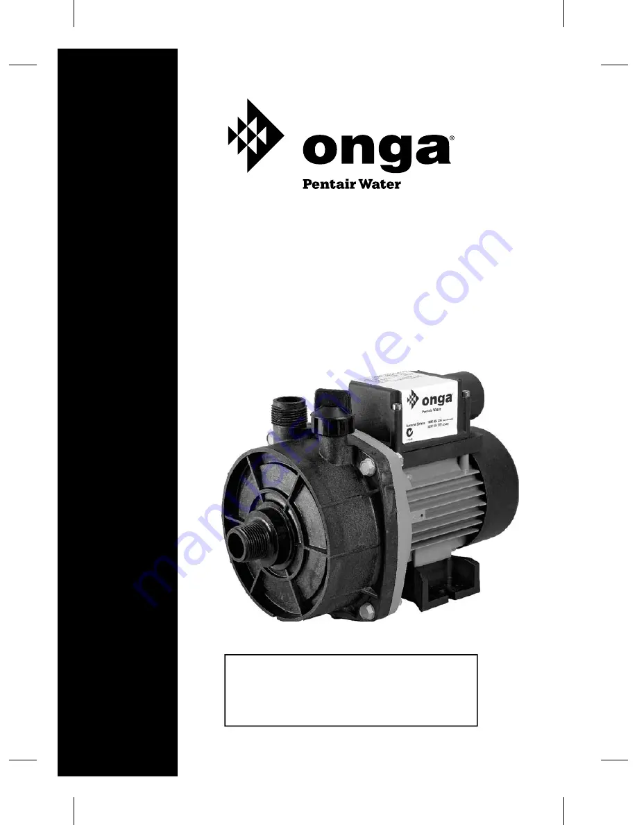
400 SERIES

HI-FLO CENTRIFUGAL PUMPS 

High head water transfer, circulation duty 

for hydroponic greenhouses, tank filling

OWNER`S MANU

AL

Should


the


installer


or


owner


be


unfamiliar


with


the

correct


installation


or


operation


of


this


type


of

equipment,


contact


the


distributor


or


manufacturer

for correct


advice


before


proceeding


with


installation

or operation


of


the


product

L100100_400Series_OM

Wednesday, 13 March 2013 9:13:38 AM

Summary of Contents for 400 Series

Page 1: ...filling OWNER S MANUAL Should the installer or owner be unfamiliar with the correct installation or operation of this type of equipment contact the distributor or manufacturer for correctadvice before proceeding with installation or operation of the product L100100_400Series_OM Wednesday 13 March 2013 9 13 38 AM ...

Page 2: ... dealer network throughout Australia and worldwide are second to none We invest considerable time and resources training and supporting them through the Onga Training Academy Congratulations on your decision to purchase an Onga product Onga is one of the best known brands in its field with a proud local and International reputation Onga is a brand for reliability value for money and technological ...

Page 3: ...ction Discharge 1 BSPM 1 BSPM 413 416 417 1 BSPM 1 BSPM 414 415 IP Rating IP55 Motor Frequency 50Hz Maximum Working Pressure 145kPa 413 160kPa 414 220kPa 415 190kPa 416 260kPa 417 Maximum Fluid Temperature 70 C o Maximum Ambient Temperature 55 o C Model Part Number Description kW 413 341300 413 Medium Head Pump 0 37 414 341400 414 Medium Head Pump 0 37 415 341500 415 Medium Head Pump 0 75 416 3416...

Page 4: ...motor for correct voltage See Electrical section of this manual and motor label Ground motor before connecting to power supply Meet National or local electrical code for all wiring Do not touch an operating motor Modern motors are designed to operate at high temperatures To avoid burns when servicing pump allow it to cool for at least 20 minutes after shut down before handling General Safety To av...

Page 5: ... pump casing is not strained by the pipe weight or misalignment d Suction To maintain optimum performance from your pump the suction pipe should be Kept to the shortest length possible place the pump as close to the water source as possible Re enforced crush resistant non collapsible hose or pipe All fittings should be air tight Pipes should be equal to or larger than the diameter of the suction i...

Page 6: ...t exceed the maximum pressure of the pump by an appropriate safety factor f Valves Onga recommend the use of a shut off valve in the discharge pipe to assist when maintenance is required Closed loop systems or applications where the pump is installed vertically higher than the water source will require an addi tional check valve or footvalve L100100_400Series_OM Wednesday 13 March 2013 9 13 38 AM ...

Page 7: ...7 L100100_400Series_OM Wednesday 13 March 2013 9 13 39 AM ...

Page 8: ... earth leakage or residual current protection device must be fitted to all installations rated residual operating current not exceeding 30mA A voltage surge protector should be fitted as voltage spikes or incorrect voltage can cause fire or seriously damage the motor Install ground and maintain this pump in accordance with electrical code require ments Consult your local building inspector for inf...

Page 9: ...le phase motors are supplied as standard with on winding thermal overload protection and are designed to plug directly into a 10 amp GPO domestic power supply to local electrical authority specifications OPERATION Priming the Pump Suction lift installations NOTICE Priming refers to the pump expelling all air in the system and beginning to move water from its source out into the system It does not ...

Page 10: ...sion and scalding If pump is run continuously at no flow that is with discharge shut off or with out priming water may boil in pump and piping system Under steam pressure pipes may rupture blow off fittings or blow out of pump ports and scald anyone near To prevent explosion do the following A Ensure discharge valve hose nozzle etc is open whenever pump is running B If pump fails to produce water ...

Page 11: ... baffle from motor and place on flat surface face down Use a screwdriver to push ceramic seat out from seal cavity see Figure B INSTALLATION OF FLOATING SEAL Figure C 1 Clean polished surface of floating ceramic seat with clean cloth 2 Turn seal plate over so seal cavity is up clean cavity thoroughly 3 Lubricate outside rubber surface of ceramic seat with silicone based lubricant ensuring no lubri...

Page 12: ...L UNIT Figure D 2 Reinstall seal plate using extreme caution not to hit ceramic portion of seal on motor shaft 3 Inspect shaft to ensure that it is clean 1 Clean face of sealing washer with clean cloth 4 Lubricate outer face of rubber drive ring with silicone based lubricant ensuring no lubricant touches the polished face and slide assembly on motor shaft sealing polished face first until rubber d...

Page 13: ...trying to push too high a column of water If so a higher head pump is required No power at outlet Use another electrical appliance that is known to work to check the power outlet Blown fuse Check fuse and replace if necessary Incorrectly sized pipe Check pipe work pressure losses and replace with larger diameter pipe if required Motor burnt out due to voltage spike or flooded by water The motor ma...

Page 14: ...the casing bolts Check the alignment and condition of the casing o ring before retightening the bolts Replace the o ring if leaking persists Replace the mechanical seal Pump not running Check power supply No water Gate valve closed Open gate valve Foot valve leaking Check foot valve for seal fix or replace if necessary Air lock Check suction line for humps Have your local pump professional prime t...

Page 15: ... Seal Plate Baffle 1 4 O ring Casing 1 5 Diffuser 1 6 Mechanical Seal 1 7 Impeller 1 8 Casing 1 9 Screw Casing 4 10 Priming Cap 1 11 Motor 1 12 Lead Motor 1 13 Base Screws Kit 1 Nut Casing not shown 4 REPAIR PARTS LIST L100100_400Series_OM Wednesday 13 March 2013 9 13 40 AM ...

Page 16: ...e correct details in this data sheet No responsibility will be taken for errors omissions or changes in product specifications Pentair Water reserves the right to change specifications Head Office Pentair AU NZ 1 21 Monash Drive Dandenong South Vic 3175 Australia National Customer Service Phone 1300 137 344 Fax 1800 006 688 National Dealer Locator Phone 1800 664 266 Email au sales pentair com Web ...

Reviews: