background image

V.  General Assembly

Pro 2000 Owner’s Manual

O.A.S. 2007

c

6

Cyclone

Barrel

Cone

Square to Round

Connects to Inlet

1. Motor/Blower Assembly  BXI012309-1ph - - 3ph

     1a. Fan Wheel - BWX159800

          Magnetic Starter w/ Remote Option: 1 phase

             1b. Motor Starter - AMR221417 1phase only

             1c. Cord Connector - WWC027063 1 phase only

             1d. Cord Connector Locknut - WCN340000 1 phase only

             1e. 5hp Motor BMZ050170 - 1 ph / BMZ050370-3 ph

             1f. Motor Plate - RMP002301

         Magnetic Starter not factory wired 3 phase

               Enclosed contactor with 220v coil - AMC183600

               Overload 12-18 amps - AMO121800

               Start Stop Push Button - AMP000000

2. Fan Housing - BHX030009
3. Cyclone Barrel - SXI002309
4. Cyclone Cone - SCX002309
5. Plenum Assembly for Filter 8” Elbow - FPX010300
    5a. Thumb Nut (4) - AFT000001
    5b. Cartridge Filter Threaded Clamp (4) - AFX000000

5b1.  AFB155180  Bolt 5/16-18 x 2 1/2”

    5c. Fender Washer 5/16” (4) - AFW170000
    5d. Dust Pan 4” - FPZ016040
    5e. Hardware Kit - AHX000000
        

f1. (14) 3/8” Washers - AFW190000


f2. (7) 3/8” Wiz Nuts - AFT00004


f3. (7) 3/8” x 1” Bolts - AFS015100


f4. (12) 5/16” x 1” Bolts - AFB155190


f5. (24) 5/16” Washers - AFW180000


f6. (28) 5/16” Wiz Lock Nuts AFT155175


f7. Gasket - RGZ000000 (25’)
f8. (3) 3/8” x 1 14” Bolts - AFS0157007

6. Internal Silencer (Pat. Pend.) - BSC180000
7. Filter - 18” Dia. x 62”L  - FCS186200
8. Owner’s Manual - ZBM000015
9. Decal - (1) Oneida Logo - ZBC000015
10. Labels
    10a. Rotation Label - ZBC000029

     10b. Caution / Exhaust Label - ZBS000004

     10c. General Caution Label - ZBS000001

     10d. Filter Maintenance Label - ZBS000007

     10e. Caution / Check Frequently Label - ZBS000006

     10f. Caution / Drum Cover Label - ZBS000005
11. Wall Bracket -Standard- SMS30000
12. Square to Round Inlet Transition to 8” dia. - BQX082000

Options for Dust Drums: OKD000000

    13. 35 Gal. Fiber Drum Kit (Standard) - SDK351001


13a. Drum Lid w/ 10” Ring - SDX001000


13b. Hose Clamp 12” dia. (2) - ACB120000


13c. 35 Gal. Fiber Drum - SDS350000


13e. Flex Hose (10” dia. x 1’) - DHF100000

    13. 55 Gal. Fiber Drum Kit - SDK551001


13a. Drum Lid w/ 10” Ring - SDX001000


13b. Hose Clamps 12” (2) - ACB120000

13c. 55 Gal. Fiber Drum - SDS550000

13e. Flex Hose (10”dia. x 1’) - DHF100000

    13. 55 Gal. Steel Drum Kit - SEK551001


13a. Drum Lid w/ 10” Ring - SEX551000


13b. Hose Clamps (2) - ACB120000


13c. 55 Gal. Steel Drum - SES550000

13e. Flex Hose (10” dia. x 1’) - DHF100000

14.Filter Efficiency Gauge 0”-5” H20 - VRG001005

  14a. Vinyl Tubing Clear 5/16” O.D. - VRV003125 (8’)

  14b. Static Pressure Tip - VRP001875

  14c. Mounting Flange for Pitot Tube - VRP010000

  14d. Filter Efficiency Gauge Bracket - FXX000000

30. Optional 55 gal. Angle Iron Stand -

   Part # STG023055


     1. Uprights - SXX000068 (4)

       2. Braces - SXX000021 (7)

       3. Feet - STX002001 (4)

Stand - Hardware Kit -

  Part # AHX021023

    A. (32) - 5/16” Bolts

          Part #  AFB155190

    B. (32) - 5/16” Wiz Nuts

          Part # AFT155175

    C. (64) 5/16” Flat Washers

          Part # AFW180000

Optional Angle Iron Stand

0

1

2 3 4

5

INCHES W.C.

14 14a

14b

14d

14c

XXK200001 - 1 phase  XXK200003 - 3 phase

f7

5

6

5a

5b

5c

7

f7

4

13b

13e

13b

13a

3

13c

5d

(8) 5/16” Washers

(8) 5/16” Nuts

(8) 5/16” Washers

(8) 5/16” Nuts

(7) 3/8” x 1” Bolts

(7) 3/8” Washers

(7) 3/8” Nuts

11

12

Optional Fan/Blower Outlet Transitions:

15. Square to 8” dia. For Fan Outlet - BQX308000 Uncrimped

15a. Square to 8” dia. For Fan Outlet - BQX308001 Crimped

2

1a

1e

1f

15 & 15a

Summary of Contents for Pro 2000

Page 1: ...tte St Syracuse N Y 13204 Phone 1 800 732 4065 315 476 5151 Fax 315 476 5044 www oneida air com Shown with optional bolt together Angle Iron stand and optional 55 gal steel drum Models may vary sligthly in appearance Baldor Dust Collector ...

Page 2: ...g or operating system Pro 2000 Owner s Manual O A S 2007 c I II III IV V VI VII VIII IX X XI XII XIII XIV XV XVI XVII XVIII XVIV 2 3 4 5 6 7 8 9 10 11 12 13 14 15 16 17 18 19 20 System Start Up Information Commercial Configurations General Specifications Fan Performance Curves Dimensions General Assembly General Assembly Instructions Bracket Assembly Filter Assembly Filter Maintenance Filter Effic...

Page 3: ... gates open Current draw should not exceed maximum motor amperage OAS is not responsible for damage to motors caused by improper installation wiring or failure to follow these directions Caution The Direct Drive Fan Blower makes the system top heavy Use extreme care when setting the unit up Warning If amperage is too high shut down immediately See troubleshooting section Warning Do not operate Fan...

Page 4: ... Filter O A S 2007 c Shown with optional Angle Iron Stand and optional 55 gal steel drum Cartridge Filter Media 1 Pleated Spun Bonded Cartridge Filter 62 130 Sq Ft Accredited independent lab tested Bathed in teflon like coating for easy dust release Captures 99 9 of Test Material from 0 2 2 microns Kit Contents 8 Ft Hose and Connection 0 1 2 3 4 5 INCHES W C Gauge Bracket Included Square to Round ...

Page 5: ...d non sparking non ferrous dynamic two planed balanced to ISO 6 3 specifications Sound 80 82dB 10 with Built in Silencer and Filter 130 Sq Ft Filter Media Spun Bonded System Fan Curve U S Made Baldor TEFC Class F 1 15 SF Single Phase 5hp Motor 208 230V 19 8A Three Phase 5hp Motor 208 230 460V 13 6 12 4 6 2A Pro Series 2000 6 4 2 0 Static Pressure at Cyclone Inlet CFM 0 200 400 600 1000 800 12 1800...

Page 6: ...mensions subject to slight variation in manufacturing Pro 2000 Owner s Manual O A S 2007 c 00 00 72 00 81 00 35 Gal Shown Add 8 for 55 Gal 62 00 4 00 8 00 18 00 18 00 27 00 53 00 60 00 1 Dimensions shown with 5 flex hose between drum and cone collars 8 00 16 00 ...

Page 7: ... 10e Caution Check Frequently Label ZBS000006 10f Caution Drum Cover Label ZBS000005 11 Wall Bracket Standard SMS30000 12 Square to Round Inlet Transition to 8 dia BQX082000 Options for Dust Drums OKD000000 13 35 Gal Fiber Drum Kit Standard SDK351001 13a Drum Lid w 10 Ring SDX001000 13b Hose Clamp 12 dia 2 ACB120000 13c 35 Gal Fiber Drum SDS350000 13e Flex Hose 10 dia x 1 DHF100000 13 55 Gal Fiber...

Page 8: ... then bolt cone to barrel Lift entire unit up onto wall braket Unit is extremely heavy and top weighted be advised Method 2 Bolt Fan Blower housing to Cyclone barrel Then bolt Motor and Plate to Fan Blower housing Put Cone up on Wall Bracket and orient holes Lift assembled unit onto cone making sure proper holes are lined up Bolt unit to bracket then finish bolting barrel to cone Method 3 Bolt Fan...

Page 9: ...el to ensure straightness 3 Attach bracket to wall with lag screws concrete anchors or other suitable hardware See Fig 2 3 Note When installing the brackets on a concrete wall mount 2 x 4 s between wall and brackets to stabilize and dampen vibration 4 Position Angle Ring around top of cone over bracket Line up one hole in Ring with hole in each bracket at desired rotation of outlet If rotation you...

Page 10: ...purchased Silencer Included For Filter cleaning instructions see pg 11 Caution If exhaust air is vented outside you must provide make up return air Flue gases carbon monoxide can be drawn into the shop from furnaces water heaters or other appliances 1 Exhaust air to exterior of building Mount directly at the hole in exterior wall or use a square to round transition and ductwork to vent air to exte...

Page 11: ...blower should not vibrate Fan wheel is dynamic two plane balanced to ISO 4 0 specifications Mount system and connect cyclone and dust bin Make sure dust bin is in place before turning on the dust collector Do not operate Fan Blower unless Cyclone and Dust Bin are in place Motor will overheat Electrical Wiring Make sure power source matches wire voltage configurations on motor Prior to connecting t...

Page 12: ...t labeled high on the back of the Pressure gauge 5 Make sure the tubing is not crushed or kinked along its entire length cut shorter if necessary 4 When the gauge rises to 3 it s time to clean your filter 2 Take the initial reading with cleaned filter s and the typical number of blast gates open in normal operation 3 Always read the gauge with the same number of gates open The more gates open the ...

Page 13: ...dry completely before reuse or keep a spare filter on hand 2 Empty Dust Bin All steps should be done with a dust mask and eye protection 3 Rinse with water Optional 1 Compressed air from outside Blast air along pleats of the filter at about a 20 angle Blast air out and away from you or anyone in the general area Keep air nozzle at least 6 from filter Closer blasts may damage filter material 6 Filt...

Page 14: ...ructions for Magnetic Starter Always use a licensed professional electrician Follow Wiring Diagram on Motor Note This Dust Collector is pre wired at the factory and need only be plugged into a NEMA 6020R dedicated electrical receptacle 5hp single phase only ...

Page 15: ...Unplug unit before servicing or cleaning 13 XIII Troubleshooting 14 Pro 2000 Owner s Manual O A S 2007 c ...

Page 16: ...ons in size 017 of an inch in certain concentration ranges when ignited can deflagrate burn quickly An ignition source such as a spark or ember can ignite a dust mixture resulting in an expanding flame front which can cause an explosion if tightly contained A disturbance that raises a cloud of accumulated fine dust can raise additional dust clouds which can cause a series of explosions that can le...

Page 17: ...e liable for death injuries to persons or property or for incidental contingent special or consequential damages arising from the use of our product Oneida Air Systems does not warrant or authorize use of wood dust collectors for other purposes This includes wood products that are treated coated or otherwise altered from their natural state Limited Warranty Products will be shipped to Buyer s sing...

Page 18: ...r s Manual O A S 2007 c XVI Stand Assembly STG023055 Bolt Washer Stand Nut 68 23 7 8 23 7 8 23 7 8 23 7 8 23 7 8 23 7 8 23 7 8 32 5 16 Bolts 32 5 16 Nuts 64 5 16 Flat Washers FRONT has no lower brace across LEFT RIGHT ...

Page 19: ...he BAG Gripper provides the ability to use convenient plastic bags inside your dust drum It provides a constant negative pressure on the outside surface of the plastic bag that keeps it pulled tight against the sides of the dust drum Can be used with 35 and 55 gal barrels Must be wired into your system The BAG Gripper 18 x 62 130 Sq Ft Spun Bonded Filters 99 9 of test material from 0 2 to 2 micron...

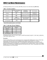
Page 20: ...ns their 2 pole motors 3600 RPM motors are to be relubricated every 5500 hours Table 1 Service Conditions Table 2 Lubrication Interval Multiplier Per Baldor specifications add 30 ounces 8 4 grams of Mobil Polyrex grease by weight or 6 cubic inches 2 teaspoons of Mobil Polyrex grease by volume ...

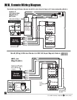
Page 21: ...at bottom of starter AMR220000 Important Remove this factory installed Jumper Wire Remote Black Box Remote is mounted inside starter top cover by using double sided tape supplied 14NO 6T3 4T2 2T1 A2 A1 13NO 5L3 3L2 1L1 18 17 Contactor 6T3 4T2 2T1 Overload 98 97 96 95 Amp Adjustment Dial YEL BRN BRN YEL RED RED YEL BRN BRN YEL RED RED BRN Retrofit Wiring of Wireless Remote into 220V OAS Import Magn...

Reviews: